The Finite Element Method
In this chapter, we considered the free-vibration analysis and modal representation for flexible structures, along with methods for solving initial-value and forced- response problems associated therewith. Moreover, the approximation techniques of the Ritz method, the Galerkin method, and the finite element method were introduced. This sets the stage for consideration of aeroelastic problems in Chapters 4 and
5. The static-aeroelasticity problem, addressed in Chapter 4, results from interaction of structural and aerodynamic loads. These loads are a subset of those involved in dynamic aeroelasticity, which includes inertial effects. One aspect of dynamic aeroe – lasticity is flutter, which is discussed in Chapter 5, where it is shown that both the modal representation and the modal approximation methods apply equally well to both types of problems.

Problems
1. By evaluating the appropriate integrals, prove that each function in the following two sets of functions is orthogonal to all other functions in its set over the interval
0 < x <1:
(a) sin (n) for n = 1, 2,3,…
(b) cos (nnx) for n = 0,1, 2,…
Use of a table of integrals may be helpful.
2. Considering Eq. (3.54), plot the displacement at time t = 0 for a varying number of retained modes, showing that as more modes are kept, the shape more closely resembles the initial shape of the string given in Fig. 3.2.
3. Compute the propagation speed of elastic torsional deflections along prismatic, homogeneous, isotropic beams with circular cross sections and made of
(a) aluminum (2014-T6)
(b) steel
Hint: Compare the governing wave equation with that for the uniform-string problem, noting that for beams with a circular cross section, J = Ip.
Answers: (may vary slightly depending on properties used)
(a) 3,140 m/s
(b) 3,110 m/s
4.
For a uniform string attached between two walls with no external loads, determine the total string deflection v(x, t) for an initial string deflection of zero and an initial transverse velocity distribution given by
16VI [m ^ 1 . /nnx
Answer: v(x, t) = T ^ n2(n2 _ 4) sin (~) Sln (“nt), where
![]() nn
nn
= —
I
5. Consider a uniform string of length I and mass per unit length m that has been stretched between two walls with tension T. Transverse vibration of the string is restrained at its midpoint by a linear spring with spring constant k. The spring is unstretched when the string is undeflected. Write the generalized equation of motion for the ith mode, giving particular attention to the writing of the generalized force Ei. As a check, derive the equation taking into account the spring through the potential energy instead of through the generalized force.
Iі + «2| + —(-1) 2 ^ (-1) 2 Ij = 0

j=1,3,…
1 + щ21 = 0
6.
Consider a uniform string of length £ with mass per unit length m that has been stretched between two walls with tension T. Until the time t = 0, the string is undeflected and at rest. At time t = 0, concentrated loads of magnitude F0 sin Ut are applied at x = £/3 and x = 2£/3 in the positive (up) and negative (down) directions, respectively. In addition, a distributed force
is applied to the string. What is the total string displacement v(x, t) for time t > 0?
+ ^2 [Dn [cos(Ut) – cos («nt)] sin (^ J
п=1,3,… £
 |
where
7. Consider a uniform circular rod of length £, torsional rigidity GJ, and mass moment of inertia per unit length p J. The beam is clamped at the end x = 0, and it has a concentrated inertia IC at its other end where x = £.
(a) Determine the characteristic equation that can be solved for the torsional natural frequencies for the case in which IC = p J£Z, where Z is a dimensionless parameter.
(b) Verify that the characteristic equation obtained in part (a) approaches that obtained in the text for the clamped-free uniform rod in torsion as Z approaches zero.
(c) Solve the characteristic equation obtained in part (a) for numerical values of the first four eigenvalues, аі £, і = 1,2, 3, and 4, when Z = 1.
(d) Solve the characteristic equation obtained in part (a) for the numerical value of the first eigenvalue, ail, when Z = 1, 2, 4, and 8. Make a plot of the behavior of the lowest natural frequency versus the value of the concentrated inertia. Note that a1£ versus Z is the same in terms of dimensionless quantities.
Answer:
(a) Zaltan(al) = 1
(c, d) Sample result: a1l = 0.860334 for Z = 1
8. Consider a clamped-free beam undergoing torsion:
(a) Prove that the free-vibration mode shapes are orthogonal, regardless of whether the beam is uniform.
(b)
 |
Given that the kinetic energy is
10. Consider a clamped-free beam undergoing bending:
(a) Prove that the free-vibration mode shapes are orthogonal, regardless of whether the beam is uniform.
(b)
Given the kinetic energy as
show that К can be written as
where Mi is the generalized mass of the ith mode and ^ is the generalized coordinate for the ith mode.
(c) Given that the potential energy is the internal (i. e., strain) energy; that is
dx
show that P can be written as
![]() p = 2J2 Mi «2 ^
p = 2J2 Mi «2 ^
where щ is the natural frequency.
(d) Show that for a uniform beam and for фі as given in the text, Mi = ml for all i.
11. Consider a uniform beam with the boundary conditions shown in Fig. 3.38 undergoing bending vibration:
(a) Using the relationships derived in the text, plot the square of characteristic value (a1l)2, which is proportional to the fundamental frequency, versus к from 0 to 100. Check your results versus those given in Fig. 3.40.
(b) Plot the fundamental mode shape for values of к of 0.01,0.1,1,10, and 100. Suggestion: use Eq. (3.270). Check your results for к = 1 with those given in Fig. 3.39; your results for к = 100 will not differ significantly from those in Fig. 3.41, in which к = 50.
12. Find the free-vibration frequencies and plot the mode shapes for the first five modes of a beam of length l, having bending stiffness EI and mass per unit length m, that is free at its right end, and that has the sliding condition (see Fig. 3.26) at its left end. Normalize the mode shapes to have unit deflection at the free end and determine the generalized mass for the first five
modes. ________ _____________________
Answer: щ = 0, щ = 5.59332^EI/(ml4), щ = 30.2258^EI/(ml4), щ =
74.6389^EI/(ml4), «4 = 138.791^EI/(ml4); M0 = ml and Mt = ml/4 for i = 1, 2,…, to. As a sample of the mode shapes, the first elastic mode is plotted in Fig. 3.48.
13. Consider the beam in Problem 12. Add to it a translational spring restraint at the left end, having spring constant к = к EI/l2. Find the first three free-vibration frequencies and mode shapes for the cases in which к takes on values of 0.01,1, and 100. Plot the mode shapes, normalizing them to have unit deflection at the free end.
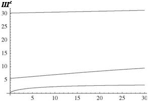
Answer: Sample results: A plot versus к of (a, l)2 for i = 1, 2, and 3 is shown in Fig. 3.49, and the first mode shape for к = 1 is shown in Fig. 3.50.
14. Consider a beam that at its left end is clamped and at its right end is pinned with a rigid body attached to it. Let the mass moment of inertia of the rigid body be given by Ic = ц-ml2 where C coincides with the pin (i. e., a pirot).
(a) Find the first two free-vibration frequencies for values of л equal to 0.01, 0.1, 1, 10, and 100. Comment on the variation of the natural frequencies versus л.
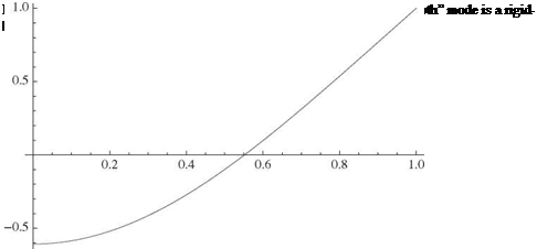 |
Figure 3.49. Variation versus к of (a, l)2 for i = 1, 2, and 3, for a beam that is free on its right end and has a sliding boundary condition spring-restrained in translation on its left end
x
0.2 0.4 0.6 0.8 1 7
(b) Choose any normalization that is convenient and plot the first mode shape for these same values of д. Comment on the variation of the mode shapes versus д.
Answer:
(a) Sample result: = 1.99048^^17 for д = 1.
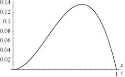
(b) Sample result: The first mode shape for д = 1 is shown in Fig. 3.51.
15. Consider a uniform clamped-free beam of length l, bending rigidity El, and mass per unit length m. Until time t = 0, the beam is undeflected and at rest. At time t = 0, a transverse concentrated load of magnitude F cos(Q. t) is applied at
x = l.
(a) Write the generalized equations of motion.
(b) Determine the total beam displacement v(x, t) for time t > 0.
(c) For the case when ^ = 0, determine the tip displacement of the beam. Ignoring those terms that are time dependent (they would die out in a real beam because of dissipation), plot the tip displacement versus the number of mode shapes retained in the solution up to five modes. Show the static tip deflection from elementary beam theory on the plot. (This part of the problem illustrates how the modal representation can be applied to static – response problems.)
![]()
![]()
![]()
![]()
![]()
 |
Figure 3.51. First mode shape for a beam that is clamped on its left end and pinned with a rigid body attached on its right end with д = 1
 |
Answer:
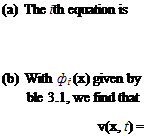 fi + afe = 2(—1)+lF cos(Qt) ml
Eq. (3.258), a = (al)2JmL, and ail as given in Ta – 2 F ^ (—1)+1
mill шг_ Q2 [cos(Qt) — cosM)]Фі(x)
i=1 i
(c) The result converges within engineering accuracy to FE= using only a few terms.
16. Consider a free-free beam with bending stiffness EI, mass per unit length m, and length l. Applying the Ritz method, write the equations of motion for a system that consists of the beam plus identical rigid bodies attached to the ends, where each body has a moment of inertia IC and mass mc. Use as assumed modes those of the exact solution of the free-free beam without the attached bodies, obtained in the text. Note the terms that provide inertial coupling.
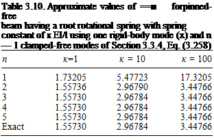
17. Consider a pinned-free beam with the rotation about the hinge restrained by a light spring of modulus к EI/l. Use a rigid-body rotation plus the set of clamped-free modes as the assumed modes of the Ritz method. Compare the
|
l4 Table 3.11. Approximate values of a2J = for pinned-free beam having a root rotational spring with spring constant of к EI/l using one rigid-body mode (x) and n — 1 clamped-free modes of Section 3.3.4, Eq. (3.258)
|
cor pinned-free beam
|
Table 3.12. Approximate values having a root rotational spring with spring constant of к EI /l using one rigid-body mode (x) and n — 1 polynomials that satisfy clamped-free beam boundary conditions
|
results for the first two modes using a varying number of terms for к = 1,10, and 100.
Answer: See Tables 3.10 and 3.11.
18. Repeat Problem 17 using a set of polynomial admissible functions. Use one rigid-body mode (x) and a varying number of polynomials that satisfy all the boundary conditions of a clamped-free beam.
Answer: See Tables 3.12 and 3.13.
19. Consider a clamped-free beam of length l for which the mass per unit length and bending stiffness vary according to
m = m0[1 — i + xj)
E = EI0 (‘ — l + к j)
Using the comparison functions in Eq. (3.325), apply the Ritz method to determine approximate values for the first three natural frequencies, varying the number of terms from one to five. Let x = к = 1/2.
Answer: See Table 3.14.
20. Rework Problem 19 using the Ritz method and the set of polynomial admissible functions (x/l)1+1, i = 1, 2,…, n
Answer: See Table 3.15.
|
Table 3.13. Approximate values of &>2y E4 for pinned-free beam having a root rotational spring with spring constant of к EI/l using one rigid-body mode (x) and n — 1 polynomials that satisfy clamped-free beam boundary conditions
|
|
Table 3.14. Approximate values of for a tapered, clamped-free beam based on the Ritz method with n polynomials that satisfy all the boundary conditions of a clamped-free beam
|
21. Rework Problem 19 using Eq. (3.329) with f = 0 as the equation of motion and the set of polynomial comparison functions (x/£)‘+1, i = 1, 2,…, n.
Answer: See Table 3.16.
22. Consider a clamped-free beam to which is attached at spanwise location x = lr a particle of mass pml. Using a two-term Ritz approximation based on the functions in Eq. (3.325), plot the approximate value for the fundamental natural frequency as a function of r for p = 1.
ans.: See Fig. 3.52.
23. Consider a clamped-free beam undergoing coupled bending and torsion. Set up an approximate solution based on the Ritz method for the dimensionless frequency parameter
2 mlArn2
k2 = __
El
using the uncoupled bending and torsional mode shapes as assumed modes, and with the parameters pIp = 0.01m*2, md2 = 0.25pIp, K2 = 0.25GJ El, and GJ/EI = 5. Answer these questions: How do the signs of d and K affect the frequencies? How do they affect the predicted mode shapes?
|
Table 3.15. Approximate values of for a tapered, clamped-free beam based on the Ritz method with n terms of the form (x/lf +1, i = 1, 2, …, n
|
|
n |
-2УЇІ |
||
|
1 |
7.88811 |
_ |
_ |
|
2 |
4.45385 |
54.5221 |
– |
|
3 |
4.19410 |
24.3254 |
175.623 |
|
4 |
4.33744 |
21.4784 |
67.1265 |
|
5 |
4.31379 |
23.8535 |
53.6214 |
|
Exact |
4.31517 |
23.5193 |
63.1992 |
|
Table 3.16. Approximate values of щ E – for a tapered, clamped-free beam based on the Galerkin method applied to Eq. (3.329) with n terms of the form (x/l )1 +1, i = 1, 2, …, n |
24. Repeat Problem 23 using an appropriate power series for bending and for torsion.
25. Develop a finite-element solution for the static twist of a clamped-free beam in torsion, accounting for linearly varying GJ (x) within each element. Compare results for the tip rotation caused by twisting, with identical loading and properties (i. e., GJ (0) = GJ о = 2GJ (l), r (x, t) = r = const.). Note that the results in Section 3.5.3 approximate the linearly varying GJ as piecewise constant within elements, whereas here you are to assume piecewise linearly varying GJ within elements.
Answer: The results do not change; see Table 3.9.
26.
Set up a finite-element solution for the dimensionless natural frequencies of a beam in bending m(0)l4«2/[EI(0)] from Section 3.5.3, accounting for linearly
Figure 3.52. Approximate fundamental frequency for a clamped-free beam with a particle of mass ml attached at x = rl
|
Table 3.17. Finite-element results for the natural frequencies of a beam in bending with linearly varying EI(x), such that EI(0) = EI0 = 2EI(l) and values of EI are taken as linear within each element
|
varying EI(x) and m(x) within each element. Compare [ M] and [ K] matrices obtained for the case developed in the text (i. e., piecewise constant EI and m within elements) with those obtained for linearly varying within elements. Tabulate dimensionless frequencies for the first three modes, assuming elements of constant length, EI(l) = 0.5EI(0), and m(l) = 0.5m(0).
Answer: See Table 3.17.

The finite element method is, by far, the most popular way of solving realistic structural dynamics and aeroelasticity problems in industry. The name derives from the breaking of a structure into a large number of small elements, modeling them approximately, and connecting them together appropriately. Because of this way of discretizing the geometry, it is possible to accurately capture modeling details that other methods cannot.
In one sense, the finite element method can be regarded as a special case of Ritz and Galerkin methods, one in which the generalized coordinates are themselves displacements and/or rotations at points along the structure. It typically makes use of polynomial shape functions over each of the finite elements into which the original structure is broken. Equations based on the finite element method have the same structure as Eq. (3.304); however, they are typically of large order, with n being on the order of 102 to 107. What keeps the computational effort from being overly burdensome is that the matrices have a narrow-banded structure, which allows specialized software to be used in solving the equations of motion that takes advantage of this structure, reducing both memory and floating-point operations and resulting in significant computational advantages.
Here, we present only a simple outline of the method as applied to beams in torsion and in bending, leaving more advanced topics such as plates and shells to textbooks devoted to the finite element method, such as those by Reddy (1993) and Zienkiewicz and Taylor (2005).
Application to Beams in Torsion. Here, we use the finite element method to analyze the behavior of a nonuniform beam in torsion. Similar to the application of the Ritz method, we make use of Lagrange’s equation. Regardless of how finite elements are derived, however, for a sufficiently fine mesh, the results should approach the exact structural behavior. This development encompasses both forced response and free vibration.
Consider a clamped-free beam subjected to a distributed torque r (x, t) as depicted in Fig. 3.44. Note that the x coordinate is along the beam. The strain energy
where GI (x) is the torsional stiffness of the wing and в (x, t) is the elastic twist. In the finite-element approach, the beam is divided into n elements, as shown in Fig. 3.45. Although there is no requirement to make the elements of constant stiffness, we do so for convenience. Relaxation of this assumption is left as an exercise for readers (see Problem 25). Element i is connected to two end nodes i and i + 1 with coordinates Xi and xi+1, respectively. Within element i, the torsional stiffness is assumed to be a constant, GI і. The discrete value of the twist at the node i is denoted et. The twist is linearly interpolated between the nodal values so that
e(xt)=I1 – f Ы (3334)
where
z = X(3.335) with 0 < z < 1. The expression for в (x, t) also can be written as
в(x, t) = ві (t) + [ві+1(t) – ві (t)] (3.336)
ti
where xi < x < xi+1 and ti = xi+1 – xi. Note that if all ві are zero except one, then only the element immediately to the left (element i – 1) and immediately to the right (element i) are affected (Fig. 3.46). Introducing this approximation into the strain energy, Eq. (3.333), and integrating over the beam length yields
1
![]()
|
where the array {0} stores the values of the twist at the nodes
{0(t)}Г = |_0i(t) 02(t) • • • @n+i(t)J (3.338)
The resulting stiffness matrix [К] may be written as
Note that we could add the potential energy of springs attached to ground at any nodes to represent elastic restraints.
The kinetic energy may be written as
![]() (3.340)
(3.340)
Using the same interpolation for 0 (x, t) and a constant mass polar moment of inertia per unit length in p Ipi in element i, we obtain a discretized kinetic energy of the form
![]() 1 T
1 T
К = 2 {0}T[M] {0}
(3.342)
We also could add concentrated inertia at any nodes to represent the inertia of any attached rigid bodies.
The contribution of the applied torque r (x, t) comes into the analysis through the generalized force, which may be extracted from the virtual work, given by Eq. (2.46) and repeated here for convenience as
8 W = f r (x, t)89(x, t)dx (3.343)
J0
Here, it is helpful to represent the twisting moment using the same shape functions as for в, viz.
![]() r(x, t) = ri(t) + (x – x) [fi+i(t) – ri(t)]
r(x, t) = ri(t) + (x – x) [fi+i(t) – ri(t)]
with the array
{r}T = Lr1 r2 •••r„+1j (3.345)
representing the nodal values of the applied torque per unit span. The virtual work then becomes
![]() 8W ={8в}T[D] {r(t)}
8W ={8в}T[D] {r(t)}
so that the generalized force then may be put into the form
with the loading matrix [ D given by
As for the boundary conditions, admissibility requires only that we satisfy the geometric boundary conditions (see Section 3.5.1). If we consider, for example, a clamped-free beam, we need only set в1 = 0. The boundary condition at the free end (i. e., zero twisting moment) is a “natural” (i. e., a force or moment) boundary condition, not a geometric condition. Therefore, it need not be taken into account in a solution by this approach. As a consequence, the first elements of column matrices [в} and [r} are removed; the reason the first element of the latter is removed is that 8в1 = 0, in keeping with the requirement that the virtual displacements and rotations must satisfy the geometric boundary conditions. This has the effect of removing the first row and column from each of the matrices [M] and [ K, and the first row from [ D].
The equations of motion now may be formed by use of Lagrange’s equation, as with the Ritz method. Given the approximation of the twist field in Eq. (3.336), the only unknowns of the problem are the nodal twist angles et. Thus, the equations of motion may be written as:
or
[M {в} + [K [в} = [D {r(t)} (3.350)
Although the size of the system matrices in the finite element method can be very large, these matrices possess important properties. First, as noted previously in the discussion of the Ritz method (see Section 3.5.1), they are symmetric, which here is a reflection of their having been derived from energy methods applied to conservative systems. Second, they are banded; that is, the nonvanishing entries are concentrated around the diagonals of the matrices. Third, [M is positive definite and [K is at least positive semidefinite. In the absence of rigid-body modes, [K is positive definite because it results from the computation of the strain energy of the structure, itself a positive-definite quantity when rigid-body motion is excluded.
With these equations, we may look at several types of problems for the nonuniform beam in torsion. For example:
1. The static response of the beam may be found if [r} is not a function of time. For this, we do not need the mass matrix [M]. Thus
[K] [9} = [D] {r} (3.351)
2. The free-vibration characteristics of the beam may be found by setting r = 0, assuming simple harmonic motion such that [9} = [9} exp(imt) and solving the eigenvalue problem
[K] {9} = m2[M] {9} (3.352)
3. If [r (t)} has the form [Г} exp(iШ) with [r} and ^ specified constants, the steady-state response to harmonic excitation maybe found by assuming [9 }(t) = [99} exp(i Ш) and solving the algebraic equations
[[K] – ^2[M]] {99} = [D] [r} (3.353)
4. Finally, the forced response of the structure may be determined by numerical integration of Eqs. (3.350) subject to appropriate initial conditions—that is, specified values for 9i (0) and 9і (0).
Complex structures including entire aircraft can be modeled with the finite element method. The resulting discretized equations are similar to Eq. (3.350), where [9} is an array of nodal displacements and/or rotations, {r(t)} an array of nodal forces and/or torques, [K] is a stiffness matrix characterizing the elastic behavior of the entire structure, and [M] is a mass matrix characterizing the inertia properties of the entire structure. As the complexity of the model increases, the various arrays increase in size. For the most general types of models, such as those based on three-dimensional brick elements, hundreds of thousands of degrees of freedom or more may be required to accurately model a complete wing structure.
As an illustrative example, results obtained for the tip rotation caused by twisting of a beam with linearly varying GJ(x) with GJ(0) = GJ0 = 2GJ(£), r (x, t) = r = const., and constant values of GJ within each element are presented in Table 3.9. The convergence is monotonic, and the answers are evidently upper bounds.
Application to Beams in Bending. As another example of applying the finite element method, we next turn to its application to beams in bending. The theory of bending for beams was presented in terms of strain energy, kinetic energy, and virtual work; this framework is sufficient for constructing a finite-element model for nonuniform beams in bending. Again, strictly for simplicity, we assume the bending stiffness and mass per unit length to be constants, respectively equal to EIi and mi within element i. Allowing for linearly varying EI and m within each element is
|
n |
r t2 Щ |
|
1 |
0.666667 |
|
2 |
0.628571 |
|
3 |
0.620491 |
|
4 |
0.617560 |
|
5 |
0.616184 |
|
6 |
0.615431 |
|
7 |
0.614976 |
|
exact |
0.613706 |
|
Table 3.9. Finite-element results for the tip rotation caused by twist of a beam with linearly varying GJ (x) such that GJ (0) = GJ0 = 2GJ (t), r (x, t) = r = const., and constant values of GJ within each element |
left as an exercise for readers (see Problem 26). We consider a beam loaded with a distributed force per unit length f (x, t) and a distributed bending moment per unit length q(x, t) as shown in Fig. 3.47.
As with the beam in torsion, we now develop the stiffness matrix from the strain energy. The strain energy is given by
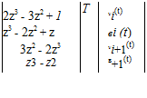
where v(x, t) is represented in terms of nodal displacements vi (t) and rotations в (t). The latter is in the sense of the bending slope в(x, t) = dv(x, t)/дx. When x is between nodes i and i +1, v(x, t) is approximated as
![]() (3.355)
(3.355)
|
|
![]() c.
c.
Figure 3.47. Schematic of a nonuniform beam with distributed force and bending moment per unit length
where
z = ^ (3.356)
with 0 < z < 1. The four cubic polynomials in Eq. (3.355) are called “Hermite polynomials.” They have the property that one of their values or derivatives at the ends (i. e., where z = 0 or z = 1) is equal to unity whereas the other three are equal to zero. This way, the element degrees of freedom are displacements or rotations at the ends of the
for the two-element case. Note that the contributions from element 1 are all in the upper-left 4×4 submatrix, whereas the contributions from element 2 are all in the lower-right 4×4 submatrix. The two overlap at the 2×2 submatrix in the middle for degrees of freedom associated with the node at the right end of element 1 and at the left end of element 2. With this pattern in mind, it is a straightforward matter to expand the matrix to an arbitrary number of elements.
The kinetic energy is given by
that with the specified interpolation can be written in discretized form as
1 T
K = 2 {1}T [M] {1} (3.361)
with the mass matrix given by
(3.362)
again for the two-element case. This pattern is the same as that of the stiffness matrix, so it is also a straightforward matter to expand the mass matrix to an arbitrary number of elements.
Finally, the contributions of the applied distributed force and bending moment are determined using the virtual work. If we interpolate both f (x, t) and q(x, t) in the same way that r (x, t) was treated for torsion, viz.
f (x, t) = f (t) + [ f+1(t) – f (t)]
‘ (3.363)
(x x )
q(x, t) = q (t) + [qi+i(t) – q (t)]
with the arrays f(t) and q(t) representing the nodal values of the applied force and bending moment per unit span
![]() {f }T = Lfi f2 •" fn+ii {q}T = Lqi q2 •••qn+ii
{f }T = Lfi f2 •" fn+ii {q}T = Lqi q2 •••qn+ii
the virtual work then becomes
![]() ~SW = {SWT [Df] {f (t)} + {Sp}T [Dq] {q(t)}
~SW = {SWT [Df] {f (t)} + {Sp}T [Dq] {q(t)}
so that the generalized force may be put into the form
and loading matrices for the two-element case given by
The contributions from element 1 are all in the upper-left 4 x 2 matrix; those from element 2 are in the lower-right 4 x 2 matrix with overlap in the 2 x 1 matrix at the center (i. e., the two middle rows of the middle column).
Because the approach is based on the Ritz method, only the geometric boundary conditions need to be satisfied. For a clamped-free beam, this means v1 = в1 = 0, so that the first two rows and columns must be removed from [M] and [K]. As for the loading matrices, Df and Dq, the first two rows must be removed because 8v1 = Sp1 = 0. The accuracy of finite elements for beam bending is illustrated in Problem 26.


