ALGORITHM FOR UNSTEADY AIRFOIL USING THE LUMPED-VORTEX ELEMENT
As was mentioned earlier, with only a few minor modifications, steady-state solution techniques can be updated to treat unsteady flows. As a first numerical example, the discrete-vortex model of thin lifting airfoils (Section 11.1.1) will be modified and the three areas of the program that will be affected are:
1. The normal velocity component on the solid boundary should include the components of the unsteady motion as well (as in Eq. (13.13a))—this is a minor and local modification to the steady-state program.
2. Similar corrections due to the unsteady motion should be included in the pressure calculations (using the modified Bernoulli equation, Eq. (13.23))— again this is a limited local modification.
3. An unsteady-wake model has to be established (e. g., the time-stepping discrete-vortex model as presented in Section 13.8.2). Note that such a wake model can be added on, in a simple manner, to the steady-state solvers.
(In this example the discrete vortex model for the thin lifting airfoil of Section
11.1.1 will be transformed to the unsteady mode. But any of the methods presented in Chapter 11 can be modified easily and can be given as a student project.)
![]()


![]()

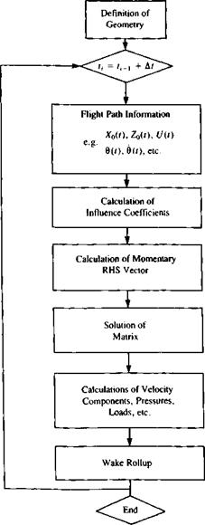
The mechanics of such an upgrade are demonstrated by the generic flow chart of Fig. 13.25. Comparing this diagram with the steady-state diagram of Fig. 9.15 reveals that, first, a time-stepping loop has to be established (only one programming statement). Then a new element appears (the flight path information block), which has all the kinematic information on the body’s or
wing’s motion. The rest of the program will follow the methodology of Chapter 11, and the only additional block is the “wake rollup” block that will perform the wake rollup at each time step. Consequently, we shall follow the same sequence used in the previous numerical chapters.
Choice of singularity element. For this discrete-vortex method the lumped – vortex element is selected and its influence is given in Section 11.1.1:
 (13.102)
where
rj = (x – Xj)2 + (z – z,)2
Thus, the velocity at an arbitrary point (x, z) due to a vortex element of circulation Гу located at (x,, zj) is given by this equation. This can be included in a subroutine, which was defined by Eq. (11.2):
(и, и») = VOR2D (Гу,, x, z, xy, z,) (11.2)
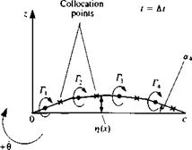
Using this lumped-vortex element, the airfoil will be represented by a set of discrete vortices placed on the camberline, as shown in Fig. 13.26. If the airfoil’s circulation changes with time, then vortex wake elements are shed at the trailing edge and the wake will be modeled by using the same discrete vortex model (Fig. 13.26).
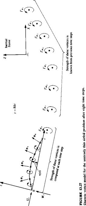
Kinematics. Let us establish an inertial frame of reference X, Z, shown in Fig.
13.27, such that this frame of reference is stationary while the airfoil is moving to the left of the page. Next, the airfoil’s camberline is placed in a moving frame of reference x, z with the leading edge at the origin. The flight path of the origin and the orientation of the x, z system is prescribed as
*o = *o(0 Z0 = Z0(r) 0 = 6(0 (13.103)
and the instantaneous velocity of the origin and the frame’s rotation 0 about

 FIGURE 13.26
x Discrete vortex model tor the unsteady thin airfoil problem (shown during the first time step, t = At)
![]()
|
|
the у axis are
X0*=X0(t) Z0 = Z0(f) 0=0(f) (13.104)
For example, if the airfoil moves to the left at a constant speed of t/„ and sinks at a speed of W„ then
X0=-U„t Y0(f) = -£4
Z0 = – w„t Z0(t) = – W. (13.105)
0 = 0, 0 = 0
Or if the airfoil flies at a constant forward speed £4, and performs pitch oscillations at a frequency со about the у axis, then
X0=-UJ, X0 (t)=-U„
Zo = 0, Z0(f) = о (13.106)
0 = sin cof, 0=co cos (at
It is useful to establish a transformation between the two coordinate systems shown in the figure such that
and similarly the transformed velocity components are
 (X_/ cos 0(f) sin 0(f) /i Z/ v—sin 0(f) cos 0(f) Ai/
The inverse transformation is also useful, and the velocity components U„ W, observed in the x, z frame due to the translation of the origin are
![]() /t/Л _/cos 0(f) – sin 0(f)/-Aro sin0(f) cos 0(f) A—Z0/
/t/Л _/cos 0(f) – sin 0(f)/-Aro sin0(f) cos 0(f) A—Z0/
 |
|
Discretization and grid generation. At this phase the thin-airfoil camberline (Fig. 13.26) is divided into N subpanels, which may be equal in length. The N vortex points (xj, Zj) will be placed at the quarter-chord of each planar panel and the zero normal flow boundary condition can be fulfilled on the camberline at the three-quarter chord point of each panel. These N collocation points (*,, Zj) and the corresponding N normal vectors n, along with the vortex points can be computed numerically or supplied as an input file. The normal n,- pointing outward at each of these points is found in the x-z frame from the surface shape tj(x), as shown in Fig. 13.27:
where the angle a, is shown in Fig. 13.26 for panel number 4. Similarly the tangential vector t, is
tі = (cos <*,, —sin a,) (13.111)
Since the lumped vortex element inherently fulfills the Kutta condition for each panel, no additional specification of this condition is required.
If the airfoil’s geometry does not change with time, then the calculation of the vortex points and collocation points can be done before the beginning of the time loop, as shown in Fig. 13.25 (where the box “definition of geometry” is placed outside of the time stepping loop).
Influence coefficients. At this point, the zero normal flow across the solid – surface boundary condition is implemented. In order to specify this condition, the kinematic conditions need to be known and the time-stepping loop (shown in Fig. 13.25) is initiated. Let us select I, as the time step counter, so that the momentary time is
t = • At
For simplicity, we assume that at t = 0 the two coordinate systems x, z and X, Z coincided and the airfoil was at rest (hence there was no wake). Consequently, the calculation begins at t = At (Fig. 13.26) and the wake at this moment consists of a single vortex Г^, which is placed along the path of the trailing edge (see Fig. 13.16, too). The location of the trailing edge at t = 0 and at t = At is obtained by using the transformations of Eqs. (13.107). The wake vortex is then placed usually at 0.2-0.3 of the distance covered by the trailing edge during the latest time step (see the discussion on this subject in the beginning of Section 13.8.2)
In general, the normal velocity component at each point on the camberline is a combination of the self-induced velocity, the kinematic velocity, and the wake-induced velocity. The self-induced part can be represented by a combination of influence coefficients, as in the steady-state flow case. If the shape of the airfoil rj(x) remains constant with time then these coefficients will be evaluated only once. The normal velocity component due to the motion of the airfoil is known from the kinematic equations (Eqs. (13.13a)) and will be transferred to the right-hand side of the equation. The velocity induced by the most recent wake vortex is unknown and will be resolved by adding an additional equation (the Kelvin condition). The strength of the other wake vortices is known from the previous time steps (for the general case when /, > 1 but since at t = At only one wake vortex is present, the rest of the wake contribution for the first time step is zero) and their effect on the normal velocity will be transferred to the right-hand side, as well.
To formulate the momentary boundary condition, let us use Eq. (13.13a), and for simplicity we allow only one component of the relative velocity vrei = (0, drf/dt) limited to small amplitudes, within the coordinate system x-z. Also, it is convenient to divide the perturbation potential into an
airfoil potential Фв and a wake potential Ф№ and both parts of the velocity potential will be modeled by discrete vortex elements of circulation Г. Consequently, the boundary condition of Eq. (13.13a) becomes
(УФВ + УФ*, – V0 – vreI – П X r) • n = 0 (13.112)
To establish the self-induced portion of the normal velocity (УФВ • n in Eq. (13.112)), at each collocation point, consider the velocity induced by the airfoil’s Tyth element at the first collocation point (in order to get the influence due to a unit strength Г, assume Г, = 1):
(u, w)v = VOR2D (Г, = 1 ,xuzu Xj, zj) (13.113)
The influence coefficient a(> is defined as the velocity component induced by the airfoil’s unit strength Г, element normal to the surface (at collocation point /). Consequently, the contribution of a unit strength singularity element j, at collocation point 1 is
au = (u, w)u – nj (13.114)
The induced normal velocity component qnl, at collocation point No. 1, due to all N vortex elements and the latest wake vortex is therefore
q„i — ЯцГі + а12Г2 + аі3Г3 + • • • + а^уГ/у + aiWrWi
Note that the strength of the airfoil vortices T; and of the latest wake vortex TW( is unknown at this point (see also Fig. 13.27 where T^, = rw„).
Fulfilling the boundary condition on the surface requires that at each collocation point the normal velocity component will vanish (Eq. (13.112)). Specifying this condition for the /th collocation point yields: а,]Г, + а,2Г2 + а,3Г3 + • • • + a, NrN + diw^w, + [C(t) + uw, W(f) + hv], • n, =0
(13.115)
where [U{t), W{t)j are the kinematic velocity components due to the motion of the airfoil and (uw, ww)t are the velocity components induced by the wake vortices (except the latest wake vortex—shown in Fig. 13.27). The wake influence can be calculated using Eq. (13.102) since the location of all wake vortex points is known. The time-dependent kinematic velocity components U(t), W(f), (see Eq. (13.49), too) are calculated with the help of Eq. (13.109):
![]() /c°s 0(0 – sin 0(f)/-*o [ g
/c°s 0(0 – sin 0(f)/-*o [ g
W(t)/ Vsin0(r) cos 0(f) A-Z0/
Since these terms are known at each time step, they can be transferred to the right-hand side of the equation. Consequently, the right-hand side (RHS) is defined as
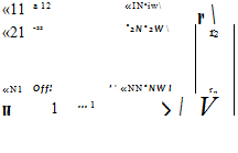
Specifying the boundary condition for each of the collocation points results in the following set of algebraic equations:
 RHSj ‘
rhs2
RHS*
m-A/) where the last equation represents the Kelvin condition,
Г(г) – Г(t – At) + TWi = 0 (13.119)
and the instantaneous airfoil circulation is the sum of all the airfoil’s vortices
Г(0 = £г,. (13.120)
This influences coefficient calculation procedure can be accomplished by using two “DO loops” where the outer loop scans the collocation points (xt, z,) and the inner scans the vortices Г,. If the airfoil camberline geometry does not vary with time [r/(jc, t) = r/(jc)], the influence coefficient calculation needs to be carried out only once at the beginning of the computations.
Establish RHS vector. The right-hand side vector, the normal component of the kinematic velocity and the wake induced velocity can be computed within the outer loop of the previously described “DO loops” by using Eq. (13.117).
Solve linear set of equations. The results of the previous calculations (shown by Eq. (13.118)) can be summarized in indicial form (for each collocation point i) as
N + l
2«,yr, = RHS, (13.121)
y=1
Again, if the shape of the airfoil remains unchanged then the matrix inversion occurs only once. For time steps larger than 1, the calculation is reduced to
N+l
r,= 2a,7’RHS, (13.122)
/ = 1
where ajj’ are the coefficients of the inverted matrix.
Computation of velocity components, pressures and loads. The resulting pressures and loads can be computed by using the Bernoulli equation
(Eq. (13.24)) near the panel surface.
Prcf-P _ Q2 ^ref ЭФ
p 2 2 dt
The pressure difference between the camberline upper and lower surfaces is then

 (13.123)
and the tangential velocity component Q, is found from
ЗФ
a = [U(t) + uw, W(t) + иv], • T; ± ■— (13.124)
‘ otj
where the ± sign stands for above and under the surface, respectively. The tangential derivative of the thin airfoil potential can be approximated as
![]() ±эф,±Х„±Л
±эф,±Х„±Л
Эт) 2 2 A/у
and here A/, is the )th panel length. (Note that here Э/Эту is used for tangential derivative and d/dt for a derivative with respect to time.)
The velocity-potential time derivative is obtained by using the definition
Ф* = ±Jo(y/2)d/:
so that the local potential is the sum of the vortices from the leading edge to the )th vortex point. After substituting these terms into Eq. (13.123), the pressure difference between the airfoil’s upper and lower surfaces becomes
ДPi = p{V{i) + »w, W(t) + ww], • Ту~j + ~ 2) rfc) (13-12?)
For example, in the case of a translatory motion parallel to the X axis, as in Eq. (13.105), and for a flat thin airfoil placed on the x axis the normal and tangential vectors become
n, = (0, 1) ty = (1, 0)
The upper and lower tangential velocity components are then
![]() Q, = u„±
Q, = u„±
and the pressure difference becomes
The total lift and moment are obtained by integrating the pressure difference along the chordline:
N
L’ = Fz = 2 Apy A/; cos ос, (13.128)
i=і
N
M0 = – 2 Apy cos о, Д/, дсу (13.129)
y=i
The drag of the two-dimensional airfoil during the unsteady motion is due to the induced angle caused by the wake and due to the added-mass effect (caused by the relative fluid acceleration, see also discussion leading to Eq.
(13.37) )
D’ = jt р("*Г, Г* Д4 sin a*) (13.130)
y=i 4 c,**=i >
Here the first term is due to the wake-induced downwash ww which in the lumped vortex element case is evaluated at the panel’s three-quarter chord point. The second term is due to the fluid acceleration (second term in Eq. (13.127)) and its center of pressure is assumed to act at the panel center.
Vortex wake rollup. Since the vortex wake is force-free, each vortex must move with the local stream velocity (Eq. (13.21a)). The local velocity is a result of the velocity components induced by the wake and airfoil, and is usually measured in the inertial frame of reference X, Z. To achieve the vortex wake rollup, at each time step the induced velocity (u, w), at each vortex wake point is calculated and then the vortex elements are moved by
(Ax, Az)i = (и, w), At (13.131)
The velocity induced at each wake vortex point is a combination of the airfoil Гу and wake Г* vortices and can be obtained by using the same influence routine (Eq. (11.2)):
N Nw
(u, iv), = 2 VOR2D (Гу, Ху., ZwXj, Zj) + 5) VOR2D (ГWk, xWi, zw., xWk, zWk) y=i *=i
(13.132)
In this simple scheme the velocity components of the current or previous (or a combination of) time step were used. But more refined techniques can be applied here that may improve the wake shape near the trailing edge.
Summary
The solution procedure is described schematically by the flow chart of Fig.
13.25. In principle at each time step the motion kinematics is calculated (Eqs. (13.103-104)), the location of the latest wake vortex is established and the RHS, vector is calculated. Then, during the first time step the influence coefficients appearing in Eq. (13.118) are calculated and the matrix equation is solved. At later time steps, the airfoil vortex distribution can be calculated by the momentary RHS; vector, using Eq. (13.122). Once the vortex distribution is obtained the pressures and loads are calculated, using Eqs. (13.128-1301. To conclude the time step, the wake vortex locations are updated due to the velocity induced by the flow field using Eq. (13.132).
As an example, consider the sudden acceleration of a flat plate (discussed in Section 13.7) placed along the x axis. The angle of attack a can be obtained by rotating the plate frame of reference by в = a relative to the direction of Q,_. For this case at t > 0 the velocity of the origin is (X0, Z0) = (-<2=°, 0) and Eq. (13.116) results in the following free-stream components
|
|
Since the normal vector to the flat plate is n = (0,1) the right-hand side (downwash) vector of Eq. (13.117) becomes
RHS, = —(Qoo cos a + uw, Qx sin a + ww) • (0, 1) = -((?» sin a + vvw)
The wake-induced downwash is obtained by using Eq. (13.113) and then at each moment Eq. (13.118) is solved for the airfoil vortex distribution. The pressure difference is then obtained by using Eq. (13.127). Results of this computation for the case of the sudden acceleration of a flat plate are presented in Figs. 13.8-13.10 along with the results obtained with the one-element lumped vortex method.
Program No. 13 in Appendix D includes most of the elements of this method except the matrix inversion phase and may be useful in developing a computer program based on this method. The matrix inversion is included, though, in Program No. 14 which is a more complicated three-dimensional model.


