BVI Acoustic Model Problem
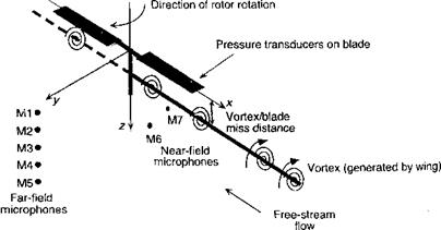
Acoustic results for an idealized BVI problem is now considered, the problem of an actual helicopter being far too complicated to explain the fundamental principles. The model is for an interaction of an elastically stiff two-bladed rotor encountering an idealized streamwise vortex parallel to the x axis, with results for both parallel and oblique (offset) cases being considered. The configuration is shown schematically in Fig. 8.49, which has been examined experimentally by Kitaplioglu & Caradonna (1994) who have measured unsteady blade loads and simultaneous acoustics data. The hover tip Mach number was 0.7 and the rotor was operated at an advance ratio of 0.2. The primary BVI event occurred over the front of the rotor disk where the blade axis was effectively parallel to the axis of the generator vortex. While a BVI event may be expected downstream as well, the effects of the hub were shown by means of flow visualization to rapidly diffuse the vortex and effectively eliminated the BVI at i/9> = 0. Experimental data for the parallel interaction case (>v = 0.0) have been made available and have been compared to predictions from various types of aeroacoustic models – see Caradonna et al. (1997).
|
Figure 8.49 Schematic showing the configuration of the idealized BVI experiment. |
![]()
|
|
 |
|
|
![]()
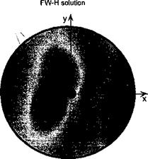
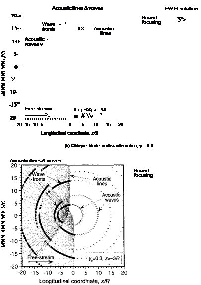
x axis upstream and downstream of the rotational axis. The ray cones appear as hyperbolic acoustic lines on the horizontal observer plane, with asymptotic slopes ± tan-1 (1 /дМпл). Wave fronts of focused acoustic energy are formed by the intersection of the closely spaced spherical wavelets generated at each of the BVI source points with supersonic trace Mach numbers. The position of these fronts at successive intervals in time (in this case every 2ж radians of rotor revolution) can be tracked by wave tracing. Notice that on the observer plane there are two sets of almost circular wavelets being generated, one from the В Vis occurring at the rear of the disk and the other occurring from the В Vis at the front. These BVI events occur half a rotor revolution apart. It will be seen that the primary wave fronts formed by the intersection of the individual groups of wavelets from each blade travel along the paths defined by the two sets of acoustic lines. Therefore, in the parallel BVI case, the sound wavelets become highly focused in directions perpendicular to the blades at = (0, jr). Notice that the results from the FW-H equation gives an acoustic directivity that is in good agreement with the results from wave tracing.
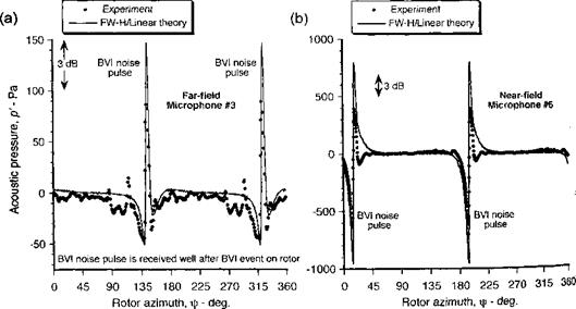
Both the near-field and far-field acoustics are sensitive to the phasing of the unsteady airloads during the BVI. In addition, the duration and phasing of the BVI event along the blade, the Doppler magnification, and the distance of the event to the microphone location combine to produce the net sound pressure signature at a given time. The thickness sound pressure further combines with the loading term, resulting in small variations in phasing that can significantly affect the net noise signature from the rotor. Comparisons of the sound pressure obtained using theory and experiment are given in Fig. 8.51 for a far-field and nearfield microphone location. Notice that the far-field sound pressure consists of two В Vi-type pulses, one being generated by each blade as it passes the vortex. The other fluctuations are background noise. The phase of the pulse in time with respect to rotor position depends on the distance to the microphone location. In this case, where the blade and vortex axes
|
Figure 8.51 Comparison of sound pressures using FW-H/linear method with experimental measurements for the parallel (yv = 0.0) BVI case, (a) Far-field microphone 3. (b) Nearfield microphone 6. See Fig. 8.49 for microphone locations. Vortex at z/c = —0.25, tip Mach number = 0.7, vortex strength Tv = —0.36. |
are parallel, there is essentially one BVI event and all points on the blade produce a sound wave that is in-phase with each other. The agreement of linear theory with experiment is good, both in terms of the peak-to-peak and the character of the acoustic pressure pulse but with an overprediction of peak-to-peak pressure. This seems typical of most computational aeroacoustic methods for reasons that are likely related to nonlinear aerodynamics.
Because the large majority of BVIs on the rotor involve oblique interactions, it is important to understand their aeroacoustic effects. Aerodynamically, the oblique BVI cases produce significant 3-D unsteady airloads. Also, the directivity of the acoustics is somewhat more complicated in this case. The extension of the problem to oblique BVIs provides a good challenge for any aeroacoustic method and, in the first instance, avoids the complexities of the real rotor wake. The obliqueness of the vortex to the blade can be obtained using various offset distances (yv) between the vortex and the longitudinal axis. When the vortex is offset laterally from the longitudinal jc axis, the BVIs with the blades are no longer parallel. This means that there are fewer points along the blade that have supersonic trace Mach numbers. The radial location of the BVIs points in this case can be found using
The corresponding trace Mach numbers are л, , ,ч MUR(rv + fisin fb)
MrOv. fb) =———— ;—- :———- , (8.252)
tan fb
|
-er! ri \/i tVi fafararknA Uift V 4/t/U 7T/Z. TTuu ivi^iuj jrig. it can be seen that with a starboard offset of the vortex to yv > 0 the acoustic lines are now directed toward the front of the rotor disk (i. e., into the second and third quadrants). Because of the varying supersonic trace Mach number in the oblique BVI cases, the focused sound waves radiate over a much larger spread angle. Notice that again the results from the FW-H equation predict an acoustic field that is in good agreement with the directivity suggested by the acoustic lines. While the results in Fig. 8.50 represent a discretization of the problem into a finite number of radial blade elements and supersonic source points, each of the solutions in Fig. 8.50(a) and (b) have been computed with the same resolution,[37] and therefore, the concentration of acoustic lines and wavelet fronts can be compared directly. |
where the blade/vortex intersection angle is у = fb and Mq. r — SIR/a. It is easily deduced that with increasing values of yv fewer intersections points will have values of у that result in supersonic trace Mach numbers. For the special case where yv — 0, the BVIs lie all along


