Principles of Noise Produced by Unsteady Forces
The intensity and directivity of the noise generated by a helicopter is of considerable importance in both civilian and military operations. The field of aerodynamically generated noise is called aeroacoustics and in the case of helicopter rotors it involves several distinct areas of study – see Schmitz (1991) and Brentner & Farassat (2003). Today there are strict certification and community noise constraints that apply to helicopters, especially during takeoffs and landings – see Lowson (1992). There is also a need to abate noise to reduce detectability in military helicopter operations.
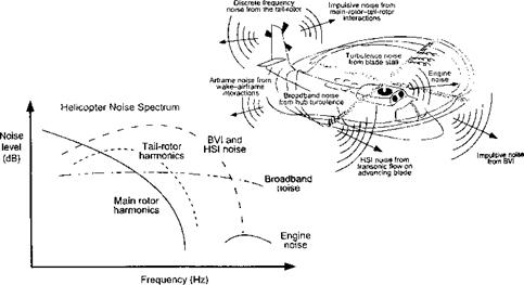
One obtrusive source of noise from a helicopter is from the main rotor, which generally occurs at low frequency and high amplitude. It is often referred to as discrete frequency noise. There are two types of discrete frequency noise, namely blade vortex interaction or BVI noise and high-speed impulsive or HSI noise – see Fig. 8.43. The tail rotor (if one is used) is also a contributor to the overall noise spectrum of a helicopter, tail rotor noise being of higher frequency and often appearing over a wider range of frequencies. Engine noise tends to be at higher frequencies. Other types of noise, called broadband noise, comes from a variety of sources such as boundary layer noise, airframe noise, including ingestion of other parts of the wake and turbulence into the rotor. A plethora of models exist to predict helicopter rotor acoustics these ranging from purely empirical methods to wave tracing methods, to blade element type unsteady aerodynamics models coupled with Ffowcs Williams-Hawking’s (FW-H) methods, to modern CFD-type methods.
|
Figure 8.43 Helicopter noise has many different sources and appears at many different frequencies with different intensities. Adapted from Edwards & Cox (2002). |
A large proportion of noise is generated by the unsteady aerodynamic forces, such as interactions of the blades with the wake or with discrete tip vortices, the so-called В VI problem, which has been discussed previously in Section 8.16.4. See Widnall (1971), George (1978), Schmitz & Yu (1986), and Schmitz (1991) for detailed discussions of the BVI noise phenomenon. BVI noise can become stronger when the leading edge of the blade becomes parallel to the axis of the tip vortex, which occurs primarily on the advancing and retreating sides of the rotor disk in forward flight. The BVI noise problem can be especially acute during descending low speed forward flight or during maneuvering flight, where the tip vortices tend to lie closer to the rotor.
Tne nigniy j-d unsteady aerodynamics produced ny tne various cvi events on tne oiaues give rise to multiple noise sources with different directivity and phase relationships. The net sound field, therefore, comprises complicated interfering omnidirectional traveling sound waves, but often highly focused, acoustic wave paths are produced as well. Besides the high computational cost of finding the rotor airloads themselves, which almost certainly will involve the use of unsteady aerodynamic models and free-vortex wake models (see Section 10.7.6). high costs are associated with evaluating the acoustics after the airloads are determined. For example, a typical acoustics calculation may use tens of thousands of observer points to map out the sound field from the rotor, so it becomes very expensive to systematically map out the directivity of the critical regions in the acoustic field. Furthermore, because of the typically pronounced directivity associated with BVI noise there is a very real possibility that localized regions that experience sound focusing effects can be missed, even by using very large numbers of observer points. This may result in misleading comparisons between different rotors and/or at different flight conditions. Overall, the prediction of the noise from a helicopter continues to be an extremely challenging research problem from both a theoretical and applications perspective; see Brentner & Farassat (2003) for a good review of the field.
Because of the complicated wake structure on an helicopter rotor in forward flight, where vortices can lie at many different orientations and inclinations with respect to the blades (see Figs 10.12 and 10.13), it has not yet proven possible to model the aeroacoustics of a helicopter rotor to the fidelity necessary for acceptable predictions without empirical correction, nor with reasonable computing costs. Most aeroacoustic models, however, have been shown to give good noise predictions for idealized problems, such as the interactions of blades with rectilinear-type vortices – see Caradonna et al. (1997) and Sim et al. (1997) for comparisons for idealized problems using different approaches. Several idealized BVI experiments have also been conducted – see Surendraiah (1970), Seath et al. (1987), Kokkalis & Galbraith (1986), Kitaplioglu & Caradonna (1994), and Kitaplioglu et al. (1997), who have provided valuable measurements to validate aeroacoustic predictions.
Most of the recent work on modeling the aeroacoustic effects of BVI, however, has con – t eentrated on complete CFD solutions, an example being given by Strawn (1997). However, ?. complete first-principles based CFD approaches for rotor aeroacoustics are not yet practical,
; in part, because of significant numerical dissipation and dispersion errors (see Chapter 14). Furthermore, while coupled CFD based methods have provided much insight into various Jotor aeroacoustic phenomena they are still only research tools and far too computationally expensive for routine use or for the parametric studies that would be necessary for rotor design. Bearing in mind that any aeroacoustic model must be properly coupled to a structural adynamic model of the rotor blades, and perhaps also to a flight dynamics simulation, there _,are clearly many limitations on what quantitative level of acoustic predictive capability for elicopters can be genuinely achieved in the shorter term.
Observer location
 •———–
•———–
8.19.1 Retarded Time and Source Time
A key issue in any acoustic problem is the determination of the time of arrival of sound waves at a given observer location in 3-D space. The evaluation of the acoustic field requires accounting for either the time of emission of a sound wave from a source point relative to the current or observer time (i. e., a retarded time calculation), or the time of arrival of a sound wave relative to a given source time (i. e., an advanced time calculation). Acoustic waves travel at the speed of sound plus or minus the local velocity of the fluid in which the waves propagate. This may be a nonuniform velocity field, which of course requires that this he known a priori for the acoustics calculation. For example, in a stationary flow the retarded time of the emission of a sound wave after it has traveled a distance R to reach the observer at time t is given by
R
r = r = t———– , (8.245)
a
or in a flow with velocity v in the direction of R the retarded time is
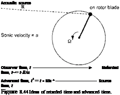
Of course, this means that the intensity of the acoustic source on the rotor must not be evaluated at the present time but according what happened at a past or retarded time, as illustrated schematically in Fig. 8.44. This is essentially a temporal mapping process and is fundamental to any type of acoustic calculation. Of course, for a rotor this retarded time problem increases the complexity of the acoustic calculations tremendously because for a given observer time all of the contributions to the sound at each observer point will have different retarded times – see Fig. 8.45. It is the evaluation of all the retarded times for points all over the rotor that adds significantly to the net computational cost of the problem.
Alternatively, to avoid a retarded time calculation the time of arrival of sound waves at the observer can be determined. This means that the future or advanced time of arrival of a wave at a given observer location is calculated using
This approach means that for a given source time all the acoustic waves must be tracked and the net sound field at a point in the acoustic field must be combined according to
the arrival time. This process was used successfully by Leishman (1996, 1999), mainly because of the large computational time savings, especially for maneuvering helicopter problems – see Brentner & Jones (2000). When using either the retarded time or advanced time formulation, the individual contributions from all wave sources from different source times are added together in amplitude and phase at each observer position and time.


