Prop Location
The decision on where to place the propeller and engine unit on the aircraft is a complex and important choice for the aircraft designer. For a single-engine aircraft should it be a tractor or pusher prop? There are many arguments for and against either layout. The Wright brothers chose pusher props on their Wright Flyer 1, and this arrangement was popular
|
The Beech 2000 Starship with twin five-blade pusher props, located at the Pima Air & Space Museum, Tucson, Ar. |
with other aircraft designers that followed. One reason early types of pushers were designed as such was to keep the propeller clear of forward firing guns. The prop’s location can also affect the aircraft’s stability, which will be covered shortly. The centre of gravity range on other types determined the prop’s location and again on other types, maybe it was just the designer’s choice. Since the WW 1 era, the trend had been more towards the tractor arrangement, with a few exceptions along the way
The USAF’s Convair B36 long-range bomber must be the world’s largest pusher aircraft ever built. It is powered by six Pratt & Whitney Wasp Major R-4360 piston-engines of 3500 BHP each, driving 19-ft. pusher props. Later models had the addition of four turbojet engines to cope with an all up weight of approximately 310,000 pounds With a wingspan of 230 feet, (larger than the Boeing 747B’s span of 195 feet 8 inches) it was at the time of its introduction the world’s largest aircraft with a first flight on 8 August 1946. The futuristic looking Beech Starship 2000 introduced in 1986 as a business aircraft, is one more relatively recent pusher type. The twin Pratt & Whitney PT-6A turboprops powered pusher props are ideally located on the trailing edge of the wing, to help place the centre of gravity well aft. The Italian Piaggio P.180 Avanti is a similar aircraft in layout to the Starship and commercially, a greater success. It was introduced in the same year as the Starship – 1986 – and is still in production at the time of this writing in 2014.
The Lake Buccaneer amphibian is another pusher type of unusual design. The single pylon mounted engine above the fuselage could well have been installed as a tractor unit. Why did the designer choose a pusher arrangement? Was it for aerodynamic reasons, or maybe to keep the prop away from spray during water take-offs and landings? The majority of prop powered aircraft, with the exceptions mentioned above, are now designed and built as tractor prop aircraft, with the
|
The Convair B-36J Peacemaker, the world s largest aircraft with pusher props. It has six P&W piston engines and four jet engines! The B-36 in this photo was the last one built, in 1956. It is on show at the Pima Air & Space Museum, Tucson, Ar. |
pusher design being an exception to the rule. However, I have digressed, so to continue…
The location of the propeller/engine affects the plane’s stability due to its position and the presence of the propwash. Although tractor props are more common, rear mounted pusher props enhance the stability. If the aircraft experiences a yaw for any reason or other, say to the left, the propwash will be deflected the opposite way to the right, and will pull the aircraft’s nose back to the right aiding directional stability. [Imagine the propwash acting in the same sense as the rudder]. The same effect occurs in the pitching plane with the propwash bending in the appropriate direction to raise or lower the nose, acting like the elevator. Both actions stabilise the aircraft. Conversely, the tractor prop may aid the stability but is mainly de-stabilising. If a tractor prop aircraft is induced to yaw to the left (as in the example above) the propwash will deflect to the right pulling the nose further to the left, resulting in a de-stabilising moment. Again, the same de-stabilising factor is present in the pitching plane.
Another de-stabilising condition is a combination of up – elevator and an increase in engine power. Consider an aircraft in the flare, about to touch down with the engine throttled back to idle power and up-elevator applied to hold off. The pilot then decides to make a late go-around and applies full power. The increase of propwash over the elevators causes an increase in elevator effectiveness that in turn, causing the nose to pitch up further, the result is a de-stabilising motion. On some high performance single-engine aircraft, the engine and propeller are not aligned with the aircraft’s axis but are tilted downwards two or three degrees and to the right by
|
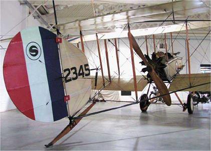
Aircraft from the WW I era used pusher props to leave the front end of the fuselage open for the gunner. This Vickers F. B.5 Gunbus is located in the RAF Hendon Museum, London. |
a like amount. The degree of nose down tilt depends on the aircraft’s power loading (weight/power). When the aircraft is flying level with a nose-high attitude, as in the landing flare, the propwash inflow to the prop disc will be parallel to the direction of flight. However, on passing through the prop disc which is tilted rearwards, the propwash will be deflected downwards and in compliance with Newton’s Third Law, this reacts on the prop disc as a nose pitch-up, combined with the thrust/drag vector, all part of the four forces acting on the aircraft. By tilting the engine and prop downwards, this places the prop disc closer to being at right angles to the propwash inflow, and therefore, reduces the downward deflection of the propwash and hence, the nose pitch-up. The outcome of this is an improvement in pitch stability.


