The Method of R. T. Jones
The results of slender wing theory were obtained by R. T. Jones in a rather simple and elegant manner in 1945. Here we shall follow some of the basic ideas of his method.
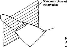
First, let’s examine the flowfleld due to a slender pointed wing in the crossflow plane (as shown in Fig. 8.22). This plane of observation is fixed to a nonmoving frame of reference, and as the wing moves across it, its momentary cross section increases. Since the flow is attached to the wing, the flowfield in
A slender wing moving across a stationary plane.
![]()
![]()
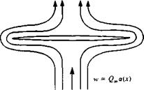
 this two-dimensional observation plane is similar to the case of a flow normal to a flat plate (see Fig. 8.23). The velocity potential difference across the plate in this flow, as was shown earlier (Section 6.5.3) is
 (8.99)
where b is the span of the plate and w is the normal velocity component (in this case w(x) = Qma(x)). However, this two-dimensional flow will not result in any forces because of the symmetry between the upper and lower streamlines. The only possibility to generate force, in this situation (with zero net circulation), is to create a change with time (e. g., due to the р(ЭФ/dt) term in the unsteady Bernoulli equation (Eq. (2.35))). Consequently, the R. T. Jones model suggests that the lift will be generated only if the fluid particles will be accelerated, relative to a “ground-fixed” observer.
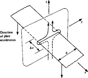
To demonstrate this principle, consider the two-dimensional plate of Fig. 8.24 as it is being accelerated downward (causing an upwash w>). The resulting force per unit length Ддс will be
 A L d_
Ajc ^ dt
(8.100)
This result can be viewed as the “added mass” of the fluid that is being accelerated by the accelerating plate. Following Newton’s second law the force

 Schematic description of the crossflow streamlines.
 |
 |
due to accelerating fluid with added mass m’ by a massless plate is
AL djm’w)
Ax dt
and by comparing this formulation with Eq. (8.100) the added mass becomes
m’ = pb2^ (8.101)
which is equal to the mass of a fluid cylinder with a diameter of b.
Now, after establishing the added-mass approach, it is possible to follow the method of R. T. Jones for the slender pointed wing. The lift on the segment of the slender wing that is passing across the plane of observation in Fig. 8.22 will be due to accelerating the added mass of the fluid:
AL d(m’w) d(m’w)dx, , .dm’
|
where w(x) = £>.<*(*), —j~ is negligible, and dxldt = Q. |
 |
Ar~d,— – jTTrMx)-fr
This equation is equivalent to Eq. (8.89), and again states that there will be no lift if b(x) is constant with x.
To obtain the lift, drag, and pitching moment, this equation is integrated, to yield the same results as presented in the previous section.


