
Our heavyweight helicopter equal in the world does not have
In Rostov started production of the most load-lifting rotary-wing car The Russian holding «Helicopt[...]

Everything about aircrafts and helicopters. News and events in aviation worldwide. Civil, transportation, military helicopters and airplanes.

Everything about aircrafts and helicopters. News and events in aviation worldwide. Civil, transportation, military helicopters and airplanes.

Everything about aircrafts and helicopters. News and events in aviation worldwide. Civil, transportation, military helicopters and airplanes.

Everything about aircrafts and helicopters. News and events in aviation worldwide. Civil, transportation, military helicopters and airplanes.


Like an aircraft, a natural flyer has to generate power to produce lift and to overcome drag during the flight. When soaring or gliding without flapping, the flyer produces much of the power required by converting potential energy to kinetic energy, and vice versa. When the flyer flaps, the power is the rate at which work is produced by the flight muscles. For basic aerodynamic concepts discussed in this section, please refer to the standard textbooks such as Anderson [44] and Shevell [46].
The total aerodynamic drag (Daero), acting on a flight vehicle, is a result of the resistance to the motion through the air. It can be divided into two components. The two drag components acting on a wing in steady flight are the induced drag (Dind), which is the drag that is due to lift, and the profile drag (D ), which is associated with form and friction drag on the wing. The drag on a finite wing (Dw) is the sum of these two components:
Dw = Dind + Dpro – (1-28)
The parasite drag (D ), which is defined as the drag on the body and only on the body, also contributes to the total drag on the bird. This drag component is caused by the form and friction drag of the “non-lifting” body (it is true that, if the body is tilted at an angle to the free-stream, it will contribute to lift, but this contribution is very small and is neglected). If the drags of the wing and body are summed, the total aerodynamic drag (Daero) of the bird can be expressed as
Daero = Dind + Dpro + Dpar* (1-29)
The different powers presented in this section are defined as the powers needed to overcome specific drags at a certain velocity. The total aerodynamic power required for steady forward flight is obtained by multiplying the drag force by the forward velocity (Uref):
Paero = DaeroUref • (1-30)
The primary goal of this section is to describe the different methods used to determine the total power required (Ptot) for flight. The power components are calculated in different ways depending on the forward velocity. Because there is a clear difference between flight at zero velocity (hovering flight) and forward flight, these two cases are dealt with separately when calculating the power components.
For hovering flight, as discussed in Section 1.2.6, the resulting velocity is essentially the same as the induced velocity (wi), which is the air speed in the wake right beneath the flyer, because of negligible forward velocity. In this case, the lift is equal to the thrust T, namely, the weight, and the total aerodynamic power required for hovering flight is
Paero = Twi• (1-31)
For forward flight, there exist three different power components corresponding to the three drag components in Eq. (1-27). The three components are the induced power (Pmd), which is the rate of work required to generate a vortex wake whose reaction generates lift and thrust; the profile power (P ), which is the rate of work needed to overcome form and friction drag of the wings; and the parasite power
(Ppar), which is the rate of work needed to overcome form and friction drag of the body. As is the case for the drag components, the power components are added together to produce the total aerodynamic power required for horizontal flight:
Paero = Pind + Ppro + Ppar, (1-32)
where Pind is the power needed for lift production during flight and decreases with increasing flight velocity. In the theory developed by Rayner [79], the upstroke is assumed not to contribute to any useful aerodynamic forces and is therefore not included. The wings are considered only to move in the stroke plane (i. e., no forward or backward movement). The induced power is calculated from the kinetic energy increment in the wake from a single stroke. The shed vortex rings are elliptical and inclined at an angle to the horizontal. The kinetic energy has two components, the self-energy of the newly generated ring and the mutual energy of the new ring, with each of the existing rings in the wake. The mutual energy contribution decreases with higher forward velocities and can be neglected for velocities above the minimum power-required velocity. With this method, the induced power can be calculated as a function of the forward velocity, from the total energy increment divided by the stroke period.
Depending on the forward velocity, different methods are used to estimate the power components in Eq. (1-32). If the forward velocity is high, the unsteady effects are small and quasi-steady assumptions can give good approximations. For slow forward velocities the vortex theory is more accurate, especially when one is estimating the induced power.
In addition to the components previously introduced, the inertial power (P^) refers to the power needed to move the wings and only the wings. The most important parameter when calculating this power is the wing’s moment of inertia. Two main ways exist to obtain a low moment of inertia: to keep the mass of the wing as low as possible and to concentrate the mass as much as possible near the axis of rotation. The inertial power is typically small under medium to fast forward flight conditions and can be neglected [80]. However, for slow or hovering flight, this power must be accounted for.
The total power required (Ptot) for flight is the sum of the total aerodynamic power and the inertial power:
Note that this is only the power required for flight and is not the same as the power input [81]. Since the flight muscles are limited by their own mechanical efficiency, and all living animals are regulated by their own metabolism, the power input needed is higher than the total power required in Eq. (1-33).
The power required (P) is strongly connected to the forward flight speed. A common way of describing this relationship is by means of a power curve. For a fixed-wing air vehicle, the induced power is proportional to U-1, the profile and parasite powers to U3, and the power required is given by
![]() P – k5U-1 + k6U3,
P – k5U-1 + k6U3,
where k5 and k6 are constants.
By expressing each power component as a function of velocity, P = f (U3) and P = f (U-1), respectively, two curves can be plotted (see Fig. 1.32). The solid curve in Figure 1.32 represents the power required for steady flight of a fixed-wing aircraft.
As suggested in Figure 1.32, the most common powered flight speed curve is the U-shaped curve (further illustrated in Fig. 1.33), in which there exists a particular speed Ump, where the required power becomes a minimum value. The straight dashed line in Figure 1.33 starts at the origin and intersects the U-curve at a certain point and has the same slope. The velocity at this point is the velocity for maximum range, UMr. When flyers migrate, they need to cover a long distance for a given amount of energy and therefore tend to fly at this velocity.
For a fixed-wing flyer, as shown by Lighthill [52], Ump and UMr, are related as follows:
UMr = 1-32 Ump. (1-35)
For birds, the power curve is not necessarily U-shaped. Different researchers in the area of avian flight have come up with different shapes of the power curve [82], depending on the power components and muscle efficiency measures they studied.
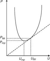
Figure 1.33. The U-shaped power curve for a fixed-wing aircraft. Ump is the velocity for minimumpower (Pmp) and UMr is the velocity for maximum range.
Figure 1.34. Comparative mass-specific pectoralis power as a function of flight velocity in cock – atiels, doves, and magpies. Bird silhouettes are shown to scale digitized from video [83].

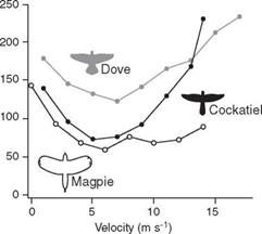 Nevertheless, as shown in Figure 1.34, the L-shaped power-flight speed curve is indeed observed in natural flyers.
