Effects of Forcing Conditions on Dynamic Stall
Dynamic stall has been extensively studied experimentally, mostly using oscillating 2-D airfoils in wind tunnels. This simulates the quasi-periodic first harmonic AoA variations that are found on helicopter rotors during forward flight. The majority of the documented experimental results are for airfoils oscillating in pitch, but there are some limited results available for plunging oscillations (vertical translation or heaving), as well as for constant angular rate (ramp) type motion. The former plunging experiments are useful in that pitch rate effects (i. e., a effects) can be isolated from the problem. The latter ramp tests are useful in that acceleration effects (i. e., a effects) can be eliminated, somewhat simplifying the understanding of the various effects produced by the airfoil kinematics on the unsteady airloads. However, both pitch and ramp experiments are difficult to perform, especially for the Mach numbers and effective reduced frequencies required to validate any mathematical model of dynamic stall.
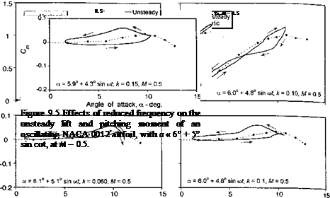
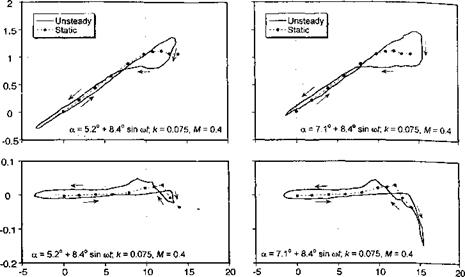
A few examples showing the variation of the unsteady airloads with variations in the oscillatory forcing parameters will now be described. With variations in parameters such as the amplitude of the AoA of the oscillation, the mean AoA, and the reduced frequency, the various dynamic stall events such as separation onset, leading edge vortex shedding, and flow reattachment all shift around the cycle to different values of AoA. This process results in significant quantitative changes in the unsteady airloads. Varying one parameter, while holding the others nominally constant can help to provide a better understanding of the physics of dynamic stall. To this end, Figs. 9.4 through 9.6 summarize the effect on the lift and pitching moment for increasing mean AoA, increasing reduced frequency, and increasing Mach number, respectively. The results are for a NACA 0012 airfoil taken from Wood
|
Angle of attack, a – deg. Angle of attack, a – deg. |
|
|
|
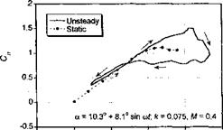
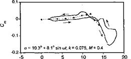
Angle of attack, a – deg. Figure 9.4 Effects of increasing mean AoA on the unsteady lift and pitching moment of an oscillating NACA 0012 airfoil at M = 0.4 with к — 0.075. |
(1979), where the airloads were obtained by integrating pressures measured using miniature pressure transducers distributed around a section of a 2-D wing (see Fig. 7.30).
Figure 9.4 shows the effects of increasing mean AoA, while holding the amplitude of oscillation at approximately 8.4° and the reduced frequency at approximately 0.075. These results show the effects on the airloads as the flow state progresses from nominally attached conditions at the lowest mean angle, through “light” dynamic stall, and into “deep” dynamic stall for the highest mean angle. These “light” and “deep” dynamic stall descriptors were suggested by McCroskey et al. (1976, 1980) and Carr et al. (1977, 1978). For the lowest mean AoA of 5.2°, Fig. 9.4 shows a typical case of stall onset. This is when the combination of forcing conditions is just sufficient to cause some minor flow separation on the airfoil. Before this occurs, however, there is a delay in the onset of lift stall to a higher AoA and to a higher value of lift compared to the static case. The airloads then show some small deviations from the attached flow behavior (which would be almost pure elliptical loops) near the maximum AoA in the cycle as a result of the limited flow separation. As the AoA is reduced on the down stroke of the cycle the flow reattaches, as indicated by the return to the nominally elliptical shapes of the loop, but it will be noted that the AoA at which flow reattachment occurs is significantly below the static stall angle.
The second case shown in Fig. 9.4 is for a mean AoA of 7.1°, which is high enough to cause stronger leading edge vortex shedding and the creation of airloads that are more typical of “light” dynamic stall. In this case the maximum dynamic lift coefficient is about 0.4 higher than the static value, but the large nose-down pitching moment is of more significance. Also, because of the clockwise loop that is now introduced into the pitching moment curve (the curve now looks like a figure eight), this forcing condition represents a situation with significantly reduced torsional aerodynamic damping.[38] The third case shown in Fig. 9.4 is for a mean AoA of 10.3°, which is high enough such that the behavior would now be characterized as “strong” dynamic stall. Leading edge vortex shedding, again, contributes significantly to increased values of lift but gives a particularly large increase in the nose – down pitching moment. Because of the higher mean AoA, now a larger part of the oscillation cycle involves partly or fully separated flow, and so there are larger hysteresis effects. There is now another large counterclockwise loop introduced into the pitching moment curve, which gives a return to high torsional damping. Flow reattachment is delayed to a fairly low AoA during the down stroke motion. This indicates the relatively long time scales required for tne flow to reorganize after strong dynamic stall has occurred and so to allow conditions conducive for flow reattachment to occur.
Figure 9.5 shows the powerful effect of reduced frequency on the lift and pitching moment responses. In the first case, results are shown for a relatively low reduced frequency of 0.06, and for an AoA history that is just sufficient to produce stall onset or light dynamic stall. The other two cases are for the same nominal AoA forcing, but the reduced frequency has been increased to 0.1 and then to 0.15. Of particular note in these cases is that vortex shedding is delayed with increasing reduced frequency until it finally occurs at the maximum AoA achieved in the cycle. This delay in stall onset is, in part, because of the kinematic induced camber effect that is associated with pitch rate (Section 8.6). This effect progressively alleviates the leading edge pressure gradients for a given value of lift and thus delays the onset of flow separation to a higher AoA. At the same time, increasing the reduced frequency also delays the onset of flow reattachment, if flow separation occurs. In the third case, it is apparent that a high enough reduced frequency can be attained to prevent flow separation from being initiated at any point in the cycle. If the mean AoA were to be increased further, then a higher reduced frequency would be required to prevent flow separation.
Finally, Fig. 9.6 illustrates the effect on dynamic stall by increasing the Mach number from 0.4 to 0.7, but under the same nominal forcing conditions, that is, for the same approximate AoA schedule and reduced frequency. It has been shown in Section 7.9.2 that the effects of compressibility manifest as a lower angle for attack for static stall onset. These effects are also found in the dynamic regime, where for the same forcing the
 |
degree of stall penetration and amount of hysteresis in the airloads are found to increase with increasing Mach number. Recall that dynamic stall onset is indicated by the break in the pitching moment. In the third case shown in Fig. 9.6, which is for a Mach number of 0.7, the dynamic stall onset involves the participation of a shock wave. This shock wave introduces a more complicated behavior in the center of pressure movement during the flow separation and reattachment process. Beddoes (1983) and Chandrasekhara & Carr (1990, 1994) give a detailed discussion of the role of shock waves in the dynamic stall process.


