Finite Wings with Flaps
Two questions are considered here: first, the calculation of C, max for a finite wing and, second, the behavior of a wing below stall with flaps.
Consider an elliptic wing, that is, one with an elliptic lift distribution. In this case the section C, is constant and equal to the wing CL. Hence at stall the section C, is everywhere the same and equal to the section CImax so that the wing CLmax must equal the section C, max. For this case, therefore, there is little or no dependence of Ctmax on aspect ratio. Next, consider a wing for which the section C, is not constant but which varies across the span. As the wing CL increases, the C, at each section must increase until finally at some section the section C, will equal the section C, max at that location. Because CL is an integrated average of the section C,’s, the highest C, at which stall first occurs will be higher than CL. Hence in this case CLmax will be less than C, max. However, for geometrically similar wings of varying aspect ratio, for example, tapered wings of the same taper ratio, CJCL is constant for the same relative spanwise location. Thus, even for a non- elliptic distribution, CLmax should not depend to any significant extent on the aspect ratio.
This nondependence of C, max on aspect ratio is shown rather clearly in Fig. 6-18. Here, both two – and three-dimensional wing data on C/max is presented as a function of Reynolds number. Little if any difference is noted between the section C, and the three-dimensional C,
CLmax is most effected by wing twist and planform taper. In order to estimate CLmax for a twisted tapered wing, we must estimate the distribution of the section C, for a given wing CL and compare the section C,’s with the section Cimax. Although elaborate lifting surface or lifting line techniques can be used to estimate the spanwise distribution of C,, it is questionable whether the accuracy of the Ctmax prediction justifies the effort. Relative effects of changes of geometry on CLmax can be predicted fairly well on the basis of Schrenk’s approximation for calculating spanwise load distributions. This approximation assumes the loading distribution to be equal to
![]()
|
4 5 6 Re x 10’* |
|
|||||||||||||||||||||||
|
|||||||||||||||||||||||
|
|||||||||||||||||||||||
|
|||||||||||||||||||||||
|
|||||||||||||||||||||||
|
|||||||||||||||||||||||
|
|||||||||||||||||||||||

![]()
Fig. 6-18. Comparison of two – and three-dimensional СІшм’s.
the average of an elliptic distribution and a distribution proportional to the chord.
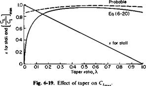
Equation (6-20) is plotted in Fig. 6-19. If CL for C, = C, max is assumed to be equal to CLmax, then (6-20) predicts less than a 7% variation in CLmax for taper ratios from 0.2 to 1.0. Actually, the variation will be less than that. Although C, may equal Cimax at one particular section, the other sections are below stall and will develop increased lift with an increase in the wing angle of attack. The ratio of CL to CLmax is therefore higher than predicted by (6-20), being more like the dashed curve in Fig. 6-19.
Most tapered wings incorporate washout, which is a negative twist of 4 or 5° that reduces the section C, near the tip and improves aileron control at high wing CL’s.
It would appear that the designer can do no wrong; C/max varies little with flap type, airfoil section, aspect ratio, or taper ratio. This is almost
true. Unless extremely thin airfoil sections or low taper ratios are used, we can expect a CLmax from a wing with full-span flaps of about 2.5 to 2.7.
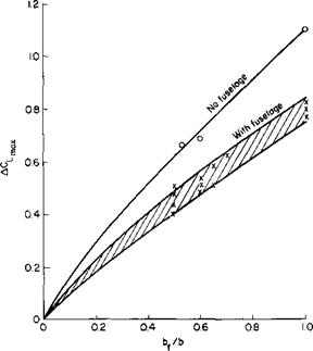
Most aircraft employ only partial-span flaps because of the span taken up by the ailerons. Thus the value of C, of about 2.7, which can be obtained with full-span flaps, is reduced to the order of 2.2 because of the incomplete flap. Experimentally and theoretically, it is found that ACimax due to flaps increases nearly linearly with the flap span. Figure 6-20 presents a limited amount of data on the variation of ACimax with bf/b, the ratio of flap span to wing span. Most of the loss in ACLmax due to ailerons can be regained if we are willing to employ “drooped ailerons.” Here both ailerons are lowered to serve as plain flaps. However, care must be taken to ensure adequate aileron control.
 |
Notice the effect of the fuselage on CLmax. From Fig. 6-18, without flaps, the fuselage has little or no effect. With flaps, however, ACLmax is reduced about 30% due to the fuselage, as can be seen from Fig. 6-20.
For flapped wings operating below the stall Ref. 1 offers a treatment of flaps that is a mixture of analytical and empirical relationships for different types. For a finite wing with partial span flaps Ref. 1 expresses ACL, based on the extended chord, as
ACL = F(A) Х^У^д) X3(^J,
where F(A) is comparable to the variation of the lift curve slope with aspect ratio, /_! is comparable to i, the flap effectiveness, k2 is equal to the product of r] from Fig. 6-8 and S, and 23 is the effect of partial span flaps. Hence, with the present notation, it is recommended that ACL below stall be calculated from
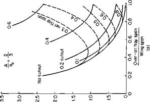
a0 is the slope of the section lift curve and is approximately equal to 0.1 C,/deg; dCJda. is the slope of the wing lift curve and can be obtained from Fig. 3-17 or Eq. (3-55); A3 is obtained from Fig. 6-20 and is equal numerically to ACLmax at bf/b divided by ACLmax for bf/b = 1.0. When a flap has a central cutout so that the spanwise positions of its inboard and outboard ends are at bfJ2 and bfJ2 from the center line, respectively, the part span correction factor is
|
|
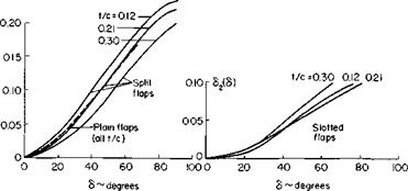
The increment in profile drag coefficient due to flaps is expressed in Ref. 1 by
АСВо = г1^)г2(5)йз^- (6-22)
The function d2(S) for different flaps is given approximately by a constant times sin2 <5.
For split flaps
d2 ^ 1.1 sin2 S.
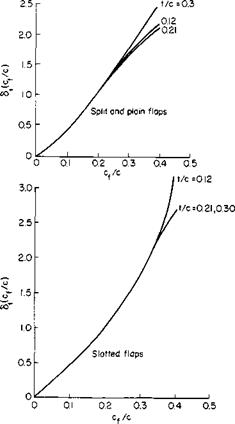
The functions and b2 are presented in Figs. 6-21 and 6-22; <53 is simply the ratio of the flapped wing area to the total wing area.
|
|
|
|
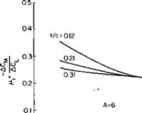
The increment in pitching moment coefficient is nearly proportional to the increment in the lift coefficient. For full-span flaps
ACM = -/x, ACL. (6-23)
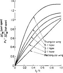
For part-span flaps (6-23) is multiplied by another function n2(bf/b).
ACM = – цфг Aci. (6-24)
|
o1—— 1—— 1—— 1—– ‘ 0 01 0.2 0.3 0.4 |
|
Fig. 6-23. Factor for calculating increment in pitching moment.
|
|
|
 |
The functions /л1 and ц2 are given in Figs. 6-23 and 6-24. Approximately = 0.25, which means that the increment in CL produced by the flap acts approximately at the center of the flap.
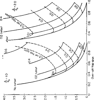
The flap may also have an appreciable effect on the induced drag. A method of correcting for this is also given in Ref. 1, in which ACD. is given by
ACDt = ^ (AQ)2. (6-25)
The function К is presented in Figs. 6-25a, b, and с; К depends on the flap span, cutout, and aspect ratio.


