Multi-disciplinary Wing Optimization-SFB-401-Wing
The task given was to optimize a wing with respect to aerodynamics, structures, and performance under considerations of static aeroelastic effects. The study involves the sizing of the wing box skins and spars to obtain minimum weight fulfilling static aero-elastic requirements (details in [7, p. 287]).
The considered MDO process chain for shape optimization of a wing including the static deformation is shown schematically in Fig. 1. The objective function is:
Obj = Wa/c x Cd/Cl, (44)
where Wa/c is the total weight of the aircraft, Cd is the overall aerodynamic drag coefficient, and Cl is the aerodynamic lift coefficient. The objective, thrust, is equivalent to the total aerodynamic drag force in stationary horizontal flight, which should be minimized.
A CATIA V5 parametric model of the wing is controlled by the optimizer using an external CATIA-DesignTable, where all relevant shape parameters for the wing are listed. The shape of airfoils at four predefined wing sections (root, kink1, kink2, and tip section) can be changed parametrically to control the thickness, camber, and twist distribution of the wing. The wing planform is fixed.
Two structure design parameters control the relative thickness change of the wing front and rear spars in combination with the upper and lower sheet thicknesses of the
|
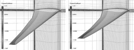
(a) Step 1, no deformation (b) Step 10, aeroelastic equilibrium Fig. 11 Undeformed and deformed wing with pressure coefficient distribution and CFD mesh for the CFD/CSM coupled iterative process. |
wing box. The stiffness and the weight of the wing are depending on these structure parameters.
Mesh deformation is a crucial component here. On the one hand, the change in geometry shape design through the parametric CAD model (CATIA V5) is treated by mesh deformation, on the other hand, the deformation of the wing structure depending on the aerodynamic forces (in addition to other forces such as fuel weight, engines, etc.) is also covered by applying mesh deformation. The CFD/CSM coupling is displayed in figure 11.
The individual components of the process chain were used in the parallel, inmemory FlowSimulator environment [1], so that a time-consuming and data intensive exchange of files was not required. Compared to the former methods, which used file exchange, significant time savings of around 50 percent have been obtained. This a major step forward in an industrial context together with the accuracy improvements and reductions of uncertainties.
In figure 12(a) and 12(b) the results of the optimization are presented. Shown is the original geometry in the aeroelastic equilibrium and the optimized geometry with a significantly different twist distribution and bending.
Figure 13 shows the convergence of the required thrust during the optimization process using a gradient free Downhill Simplex optimizer [8]. After around 80 design changes the optimum has been reached nearly.


