STALL FLUTTER
The term flutter is applied categorically to oscillations of an elastic body in a flow that is steady in the absence of the body. If, during part or all of the time of oscillation the flow is separated, then the flutter phenomenon exhibits some characteristics different from those discussed in Chapters 5-7 and is called a stall flutter.
Stall flutter is a serious aeroelastic instability for rotating machineries such as propellers, turbine blades, and compressors, which sometimes have to operate at angles of attack close to the static stalling angle of the blades. Airplane wings and tails rarely suffer from stall flutter. However, the trend toward thin wing sections and large wing span has increasingly made stall flutter of wings a serious concern for the design of highspeed aircraft.
The phenomenon of stall flutter can be best illustrated by the spinning test of a propeller. Generally, when the speed of a propeller is gradually increased, the appearance of a peculiar noise normally associated with propeller-blade flutter can be quite definitely determined. As the speed is increased beyond a value at which flutter can first be detected aurally, considerable weaving of the propeller tips can be detected visually by an observer in the plane of the propeller disk. The blade motions can be recorded by attaching, to the blades, strain gages which measure the amplitude of strain as the propeller speed changes.
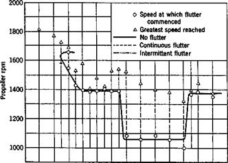
Figure 9.6 shows a typical result of the spinning test of a particular propeller obtained by Sterne.7140 The abscissa is the blade angle at 70 per cent radius of the propeller; the ordinate is the propeller speed. Above the solid curve is a region of flutter, below it, there is no flutter: Over the wide range of blade settings of this particular propeller, there are two very abrupt changes of flutter speed. These two abrupt changes divide the range of blade settings at which the propeller is tested into three regions—conveniently described as fine pitch, medium pitch, and coarse pitch. The characteristics in each region are as follows:
At very fine pitch settings, corresponding approximately to zero lift angle at the blade tips, there is no flutter in the speed range of the tests. In the fine-pitch range, the critical speed first decreases as the pitch angle is increased, and then tends to a constant value at larger angles of attack.
In the medium-pitch region, the critical flutter speed is constant, but is much lower than that in the fine – and coarse-pitch regions.
In the coarse-pitch region, the flutter speed is constant and is approximately equal to that at the coarser end of the fine-pitch region.*
Clearly, there are two distinct types of flutter. The blade settings in the medium-pitch range correspond to the stalling angles of the tip sections. In the medium-pitch range the blade stalls over part of the cycles of oscillation. In the coarse-pitch region the blade remains stalled throughout the cycles. f The flutter in the medium – and coarse-pitch regions is
|
8′ 12o 16o 20° 24° 28° 32° |
Blade angle at 0.7 radius
Fig. 9.6. Propeller flutter. Critical flutter speed against blade angle at 0.7
radius. Steady-state stalling angle of airfoil equal to 12 degrees, correspond-
ing to a blade angle of 20 degrees at 0.7 radius of propeller. Measurements
by Sterne, Ref. 7.140. (Courtesy of the Aeronautical Research Council.)
stall flutter. That in the fine-pitch region is classical flutter. The flutter motions of the blade in both regions are nearly sinusoidal.
In general, as the angle of attack is raised through the stall region, the following characteristics may be observed:
* This equality of the flutter speed in the fine-pitch and coarse-pitch regions must be regarded as a mere coincidence in this particular example.
t Stall flutter in the coarse-pitch range, i. e. at high angles of attack, resembles a forced vibration. In fact, if the speed of flow is gradually raised beyond the stall- flutter boundary at such a high angle of attack, the intensity of flutter increases rapidly at first, reaches a maximum, then decreases to practically flutter-free condition. The reason is that, at such high angles of attack, the predominant frequency in the wake (vortex street, cf. § 9.3) becomes clearly defined. The stall flutter of the wing is simply the reaction to the creation of the vortices in the wake. The phenomenon resembles the oscillation of smokestacks as analyzed in § 2.4.
1. The flutter speed drops severely.
2. The flutter frequency rises slowly toward the natural torsional oscillation frequency of the blade in still air.
3. The torsional motion predominates. Whereas in classical flutter the torsional strain and bending strain are of the same order of magnitude, in stall flutter the amplitude of the bending oscillation becomes negligibly small in comparison with that of the torsion, although the axis of rotation is in general not the elastic axis.7124
4. Usually the flutter speed reaches a minimum and rises again as the blade becomes completely stalled. The flutter amplitude becomes very small in the coarse-pitch region. The range of the angle of attack in which the violent low-speed flutter persists increases as the elastic axis is moved backward along the chord.
5. There is a large phase shift at the transition from classical flutter to stall flutter. The phase difference between the bending and torsion drops by about 45°, sometimes vanishing completely.
6. Variation of the structural properties of the airfoils has very different effects on the stall flutter as compared with the classical flutter. Change of inertia-axis location has little effect on stall flutter, which could occur even when the inertia axis lies ahead of the elastic axis when it is impossible to obtain classical flutter. The ratio of the uncoupled bending and torsion frequencies in still air has little effect on stall flutter, for which the critical speed is often higher when the ratio is equal to 1 than at other values (whereas at low angles of attack there is usually a minimum flutter speed when the bending and torsion frequencies are equal). In one case, Stiider9-26 found the critical speed to be the lowest when the wing is restrained from translatory motion and is allowed only freedom in pitch.
Stiider9-26 was the first one who studied stall flutter experimentally in great detail. In a series of tests he examined the field of flow around an airfoil oscillating about the stalling angle. His result shows that, in a stroke of increasing amplitude, the separation is delayed to an angle of attack appreciably greater than that for a stationary airfoil. On the return movement, re-establishment of a smooth flow is also delayed. Stiider calls this an “aerodynamic hysteresis” and concludes that it is the basic cause for stall flutter. This observation is supported by the earlier works of Farren and others (see § 15.4).
Thus the influence of flow separation on stall flutter is revealed through the hysteresis effect. Since the aerodynamic characteristics is nonlinear, the principle of superposition does not hold. The aerodynamic forces corresponding to different modes of motion cannot be added. Hence, an extensive experimental evaluation of the aerodynamic forces is necessary (see surveys by Victory,9,27 Halfman,9-22 and Bratt15,121)-
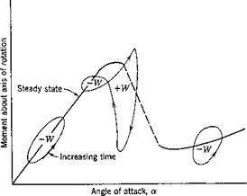
A sketch showing typical forms of the hysteresis loop corresponding to simple-harmonic oscillations in pitch is given in Fig. 9.7. At smaller angles of attack, the loop is elliptical, as predicted by the linearized theory. At angles of attack in the neighborhood of the static stalling angle, the loop is of the shape of a figure 8 (the left-hand side loop may become very small or disappear entirely, leaving a loop which indicates all positive work). At large angles of attack, the loop becomes oval again. The exact shape of the loops depend on the location of the axis of rotation,
|
Fig. 9.7. Aerodynamic hysteresis. From Halfman, Johnson, and Hayley, Ref. 9.22. (Courtesy of the NACA.) |
the reduced frequency, the amplitude of oscillation, the Reynolds number, and the airfoil shape.
The area within each loop represents the work done by the air on the airfoil in each cycle ‘of oscillation. A positive sign in front of W in Fig.
9.7 indicates an energy gain by the airfoil; a negative sign, an energy loss. The oscillation is aerodynamically unstable with respect to pitch if the net gain of energy during each cycle is positive.
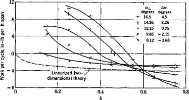
Since for a stalled airfoil the aerodynamic force produced by a simple – harmonic motion, though periodic, is not exactly simple harmonic, the work per cycle must be obtained by graphical integration of experimental results. In Fig. 9.8 is shown the work per cycle in pure pitching motion computed922 from the data obtained by Bratt and his associates9-27 (airfoil’s steady-state stalling angle 12°, elastic-axis location mid-chord, Reynolds number 1.42 X IQ5). In this figure, oq denotes the mean angle of attack, Да denotes the difference between the mean angle of attack and the steady-state stalling angle. A positive value of Да means that а,- is above the steady-state stalling angle. The amplitude of pitching oscillation is approximately 6°. Points above the W — 0 line correspond to aero – dynamically unstable oscillations. A curve corresponding to the linearized
|
Fig. 9.8. Work per cycle in pure pitch. Elastic axis at mid-chord. Measurements by Bratt et al., Ref. 9.27, for an airfoil whose static stalling angle is 12 degrees, at Reynolds number 1.42 x 10⁵. Figure by Halfman, Ref. 9.22. The work per cycle are computed for wind speed 95 mph, semichord 0.484 ft, and amplitude of oscillation 6.13 degrees. (Courtesy of the NACA.) |
|
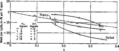
Fig. 9.9. Work per cycle in pure translation. Static stalling angle 12 degrees. Reynolds number 106. Wind speed 95 mph. Semichord 0.484 ft. Vertical translation amplitude 0.9 inches. From Halfman et al., Ref. 9.22. (Courtesy of the NACA.) |
two-dimensional theory is added for comparison. When ос,- is small, the experimental work per cycle agrees closely with the theoretical prediction (cf. Figs. 20-26 of Ref. 9.22).
Figure 9.9 shows the work per cycle in pure translation obtained by Halfman9-22 for a wing designated as “blunt,” whose steady-state stalling
angle is 15°, at a Reynolds number near 10®. It is seen that the work per cycle remains negative for the range of reduced frequencies tested. The oscillation in pure translation is therefore stable, a conclusion in agreement with the tests by von Karman and Dunn2 22 (§2.5).
Because of the nonlinear nature of the aerodynamic response, the British and American experimental results cannot be compared with each
|
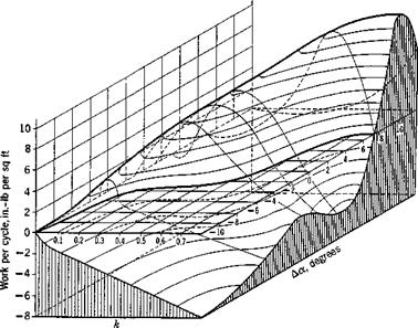
Fig. 9.10. Relief of typical variation of work per cycle in pure pitch with Да and the reduced frequency k. Wind speed 95 mph. Elastic axis location 37 per cent chord aft leading edge. Semichord 0.484 ft. Amplitude of pitching oscillation 6.08 degrees. From Halfman, Ref. 9.22. (Courtesy of the NACA.) |
other quantitatively, since the Reynolds number, the airfoil shape, and the reduced frequency range are different. But, using Да as a basis,
Да = а, — a6tall
where аг is the mean angle of attack and astall is the steady-state stalling angle, Halfman9-22 obtains an interesting qualitative comparison. From Halfman’s results9-22 in the lower к range and the British data9-27 in the higher к range, Fig. 9.10 is constructed. This figure shows qualitatively the way in which work per cycle varies with к and a. First, for a low angle of attack, the curves of work per cycle against к remain negative, quite close to the theoretical curves. At given values of к the work per
cycle gradually approaches zero as Да increases. When Да is zero, a positive work area appears at lower values of k. As Да increases further, the maximum value of positive work increases, whereas the range of positive work is narrowed but continues to move to higher values of k.
Since stall flutter is, predominantly torsional, it may be assumed, as a crude approximation, that the flutter frequency is the same as the natural vibration frequency of torsion in still air, and that stall flutter will occur when the aerodynamic work per cycle for pure pitch becomes positive and greater than the energy dissipated by the structure. From Fig. 9.10 it is seen that there is a region on the (к, Да) plane in which the work per cycle is positive. For each Да, this region is bounded by two critical values of k. Let the upper critical value of к be denoted by ker. For a given airfoil, at a given angle of attack, the value of к gradually decreases as the speed of flow gradually increases (k — oo when U = 0, the frequency со being that of the natural torsional vibration). When U reaches Ucr, where
![]() U
U
сг Ъ л’сг
a pitching oscillation of the airfoil causes no exchange of energy with the airstream, and gives a crude estimation of the critical stall flutter speed. More accurate methods of analysis are discussed in Refs. 9.22, 9.27.
Figure 9.11 shows a summary of the kcr values obtained in various laboratories. The effects of location of the axis of rotation, airfoil shape, Reynolds number R, and amplitude of oscillation 0 are revealed by the wide variation among the results.


