
Our heavyweight helicopter equal in the world does not have
In Rostov started production of the most load-lifting rotary-wing car The Russian holding «Helicopt[...]

Everything about aircrafts and helicopters. News and events in aviation worldwide. Civil, transportation, military helicopters and airplanes.

Everything about aircrafts and helicopters. News and events in aviation worldwide. Civil, transportation, military helicopters and airplanes.

Everything about aircrafts and helicopters. News and events in aviation worldwide. Civil, transportation, military helicopters and airplanes.

Everything about aircrafts and helicopters. News and events in aviation worldwide. Civil, transportation, military helicopters and airplanes.


Supersonic cruise is the longest cruise leg on those routes which arc of interest for supersonic transport. So supersonic cruise performance largely determines range, weight and cost of an SCT. Supersonic cruise performance strongly relics on aerodynamic drag reduction. Drag related weights (i. c fuel and engine size) contribute about 60^ to the SCTsMTOW (maximum takeoff weight).
Here, we concentrate on drag reduction. Although, it has to be remembered, that drag minimization for itself is no goal for an aircraft: aerodynamic performance is L/D which is Lift divided by Drag or weight divided by drag; but. when looking for performance, more weight requires an equivalent increase in fuel consumption, see e g Brcguet’s formula, cqs. (44) to (47). A careful balance must be achieved when drag reduction requires a weight increase.
To estimate the influence of individual contributions to supersonic cruise drag, we look at the composition of (supersonic) drag. Contributors are skin fnction drag, volume wave drag, lift dependent wave drag and induced drag. This is for the drag coefficient CD
C„ = A/S Cf + K, I28Vj/<hs£) + K, p2SCj/(2ic/J) + K, SC[/iKbJ) (49)
or in physical units for the drag D
D = ACfq + A„ • 128V2/{kI40) q + K, ■ tfw1 /(Inql1) + Кj ■ W2/{nqb2) (50) with
A: total surface
b; span
Cp: drag coefficient
Q: friction coefficient
CL: lift coefficient
D: drag
K|.- shape parameter for induced drag (Osswald factor)
KL: shape parameter for lift dependent wave drag
Kyi shape parameter for volume wave drag
I; lifting length
1^ total (aircraft) length
M: Mach number
q: dynamic pressure
S: wing (reference) area
V: volume (aircraft ♦ engine stream tube variation)
W: weight
and
[Г = АГ – 1 (51)
In the formulas (49) and (50) some parts are bold faced These arc the contributors which can significantly be influenced by design.
Skin friction drag:
The first term describes friction drag which is mainly determined by the aircraft’s total surface A and the friction coefficient Cf. For minimization both must be minimized.
Total aircraft surface A depends on the specified payload and the required fuel volume, aerodynamic lift, the slenderness and span requirements of other drag part minimization and (weakly) the aircraft’s mechanical strength and stiffness. The total surface minimization is no goal for its ow n, it is rather only one aspect of drag minimization to be balanced with other requirements.
Friction coefficient Cf here is the mean value of the local friction coefficients, weighted by surface area. It is mainly determined by the local Rcynolds-numbcrs. But it may be reduced by drag reduction techniques, those which are most well known arc laminarization and riblcts
Laminarization maintains the low drag of laminar flow in the boundary layer, which reduces local Cf values for an SCT by about 90%, but requires a huge technology effort (see special lecture). Presently, we design our SCTs without laminar flow, although laminar flow promises strong improvements. But an SCT which will become viable only with application of laminar flow, may loose its competitiveness with subsonic aircraft as soon as the subsonic aircraft utilizes laminar flow’. Must likely, subsonic aircraft will apply laminar flow earlier than SCTs. On the other hand, an SCT concept which is viable without laminar flow, may be improved by laminar flow just like the competing subsonic aircraft.
Riblets are streamwisc microscopic valleys in the aircraft’s surface which reduce aircraft turbulent drag locally by about 8Я (49).
Other measures to reduce skin friction may arise in ihe future. Special surface coatings (50) such as some nano materials (thickness of only a few molecules) have been proposed which alter the wall condition ("no slip") for the boundary layer flow, e g. by not completely diffuse reflection of the air molecules at the wall.
Volume wave drag:
The second term describes volume wave drag w hich is mainly determined by the aircraft’s volume V and strongly by slenderness V/l^. because l0 is squared and the whole term (V/
ly2)‘ is squared once more
Total aircraft volume V is. like surface A. given with the specified payload and the required fuel volume, the aircraft’s mechanical strength and stiffness and the slenderness and span requirements. Due to the important volume wave drag contribution, volume of
supersonic aircraft must be minimized, see Concorde’s narrow and uncomfortable fuselage.
Larger total aircraft length l0 decreases volume wave drag and decreases juncture strength as well so that it increases aircraft weight and reduces stiffness. Both have to be kept in acceptable boundaries. Especially for large SCTs. i. e. long fuselages, fuselage flexibility poses big problems.
After Concorde s first landing at the old airport in Singapore, the pilots – although carefully fixed with seat bells in the tiny cockpit – hit the overhead panels with their heads due to strong bending oscillations of the slender fuselage on the rough runway. This was. for a long time, the last Concorde landing in Singapore.
Today airports request a maximum fuselage length of about 80 m, although most large SCT-designs (250 or more passengers) have fuselages of more than 90 m which is at the flexibility and weight limits.
The shape parameter Kv depends on the volume distribution of the whole aircraft including cross sectional variations of the engine stream tubes At M= I this is simply the distribution of the area normal to the flow direction (because Mach angle ц is 90"). At higher Mach numbers it becomes more complicated:
From each point of the aircraft’s surface a perturbation wave is radiated downstream along э conoid which opens with Mach angle ц around the stream line.
sinfi = 1/Л/ (52)
the Mach conoid, see Figure 13. Therefore all areas along Mach conoids from and towards each surface point have to be respected. In practical applications for slender configurations, the following double integral approximation is used to compute the area distribution of an equivalent body of revolution: on the most important perturbation line (e. g. the fuselage center line), the contributions of one Mach cone (of the undisturbed flow) are collected by integrating the cross sectional areas which are cut by a sufficient number of tangent planes to the Mach cone, so-called Mach planes (about 24 or more), which osculate around the generating Mach cone, along the perturbation line (center line) the contributions of several generating Mach cones (about 30 or more) arc summed up (51]. see Figure 14. As long as the aircraft is slender it does not strongly alter the speed of the incoming flow; therefore the simple area approximation using the Mach planes of the incoming flow is valid. An aircraft which produces strong perturbations, will never be efficient For simple bodies of revolution, the minimum drag area distribution is given by the Sears-Haack area distribution (52). (53].
 |
Figure 13 Mach Conoid and Mach Cone
Figure 14 Wave Drag Calculation I’sing Mach Planes Lift dependent wave drag:
The third term describes the lift dependent wave drag. It depends on speed (p2 or fJ2 / q). aircraft weight W and aircraft lifting length 1.
Lift dependent wave drag rises quadraiically with weight W* or Q.2, like the induced drag in the last term. But whereas the induced drag lowers with speed (q), the lift dependent wave drag increases with speed ф" / q – l • 1/M2).
Lift dependent wave drag lowers quadraiically with lifting length l‘. requesting a slender wing with high sweep and small span.
The shape parameter KL is minimized by a smooth elliptical lift distribution along lifting length I. Computation is demonstrated in other lectures and [54].
Induced drag:
The last term describes the well know n induced drag, lb nondimenMonal value C^. which is referenced to wing area S. rises with lift coefficient squared Cl“ and decreases with aspect ratio b2/S; but in physical units it rises with weight squared W* and decreases with dynamic pressure q (speed squared) and span squared b*.
Therefore: minimum induced drag requires a high span (b‘)
The shape factor K| is the well know n Osswald factor, which becomes 1 for elliptical lift distribution over the span, see e. g. 155]. Elliptical lift distribution is achieved by plane w mgs of elliptical planform distribution and nearly by plane delta wings (as long as there is no leading edge separation). Best performance is reached with subsonic leading and tfailing edges, i. e edges within the Mach cone For supersonic edges, in general the suction force is lost which is required for minimum induced drag. Pure supersonic wings (supersonic leading and trailing edges) have the maximum lift dependent drag of
CD « Cetane* (53)
For other (wing) planforms, elliptical lift distribution can be approximated for one angle of attack by suited twist and camber distributions. Deviations of this design a produce additional induced drag according to the (wing) planform.
Summary:
To minimize supersonic drag we have to minimize certain flow parameters which requires to optimize some configuration geometry parameters:
minimize friction drag by optimizing surface geometry atul quality (lammarization). minimize volume wave drag by optimizing slenderness and -olume, minimize lift dependent wave drag by optimizing wing slenderness. minimize induced drag by optimizing span. resp. aspect ratio.
Wave drag minimization requires slender configurations and slender wings, i. e. low ЬЛ. whereas induced drag requests for high span b. Task is. to find the best combination of b and I, represented by the size of the rectangle
b 1 or b-1, (54)
given by span b and lifting length l or overall length lD(see Figure 15).
![]()
 |
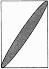 |
Classical (Concorde type) SCT
The classical Concorde-like configuration only provides relatively low span for acceptable slenderness with (at least partially) subsonic leading edges. Because the leading edge is swept in different directions, it provides only half of the maximum possible lifting length I for a given span b and sweep angle In contrast, the oblique flying wing (OFW) provides the maximum rectangle size b l=b I0 because the wing uses the whole diagonal. Indeed, the elliptical OFW’ is the best solution reaching the theoretical drag minimum which was demonstrated by R. T. Jones (561.


