Our heavyweight helicopter equal in the world does not have
In Rostov started production of the most load-lifting rotary-wing car The Russian holding «Helicopt[...]

Everything about aircrafts and helicopters. News and events in aviation worldwide. Civil, transportation, military helicopters and airplanes.

Everything about aircrafts and helicopters. News and events in aviation worldwide. Civil, transportation, military helicopters and airplanes.

Everything about aircrafts and helicopters. News and events in aviation worldwide. Civil, transportation, military helicopters and airplanes.

Everything about aircrafts and helicopters. News and events in aviation worldwide. Civil, transportation, military helicopters and airplanes.


Consider a slightly curved infinitely thin foil, moving steadily near a solid flat ground plane with an angle of pitch в. In this case with asymptotic error of the order of 0(/i2), the flow under the foil does not differ from the one-dimensional, and the channel flow potential is governed by the following elementary equations:
 |
¥>i = <Ph +hn – iph + htpз + О(h2)
![]() й,= 2^1(0) = °,
й,= 2^1(0) = °,
й,=2^(0) = -^[В1-уі(0)1птг],
where ys(x) = h + sf(x) is a distribution of the gap between the foil and the ground and f(x) = 0(1) characterizes the position of the foil with respect to the line у = h. Parameters A2 and B have been described earlier.
We construct the upper flow potential by a distribution along the segment 0 < x < 1 of two-dimensional sources (sinks) whose strength is determined on the basis of the thin body theory as [—2yf8(x)]. Additionally, one should account for the admissibility of a point source solution at the leading edge, i. e., at x = 1,2/ = 0 + 0. Note that this latter solution does not violate the flow tangency condition on the upper surface of the foil.
Thus, the values of the upper flow potential at the points of a foil on its upper surface (0 < x < 1) are given by the expression
~hipUl]
V’ui = ln(l – x)~- j y’s(£) In (a; – f) df. (3.35)
І7Г 7Г J0
The strength of the point source in accordance with (2.70) is equal to
Q = 2^±(l). (3.36)
Asymptotic expansions of a potential (pu near the edges are obtained in the following form:
Near the trailing edge,
h _//лч . hB hB2
¥?u – – ув(0)і/пі/ ———— v——— ,
7Г 7Г 7Г
where и = —x:
Bx = Q-y’s(o)-
B2 = – f y’s(0 ln£d£. Jo
The solution of equations (3.32) with boundary conditions (3.33) and (3.34) can be written as follows:
<Ph= [ y’s(£)d£ = Vs(x) -&(1) = ya(x) -1;
|
Ув([12]). |
JO
W2 = (0) + <Pi2 (1) – 92 (0);
9h = xtP3(°) + Vut1) “ ¥»I3(°)’
Uniformly valid additive expressions for the velocity potential on the upper and lower surfaces of the foil are
|
+h{<Pb*(vi) – “Ув(°) hvі[1п(тгі/і) – 1]}; |
|
9ъе(*) – Ьу’вО)^2 – ^v)] |
![]()
= ¥>+(*) – 4™) + h{<Pbe(v) – ~y’s(0 hvb(nv) – 1]}
where P — (x — l)//i, Pi = —xjh. Functions,<pае?^ье’^ье are calculated by formulas (2.43) and (2.52), in which P has to be replaced by P.
Differentiating (3.39) and (3.40) with respect to x, one can find uniformly valid expressions for the pressures on the upper and lower surfaces of the foil
|
^be* |
It is convenient to take into account the following relationships:
We calculate the lift coefficient
Cy = l[v~~v*)ix=2l (^“^r)dx=2|v+(0)“^(<))l
= 2[<pu(0) – <pi(0)] = —2[<^i(0) – hipUl (0)] + О(h2).
Setting x = 0 in expressions (3.39) and (3.40) and representing the foil ordinates as ys = h + £f(x), where /(x) = 0(1), we obtain the following formula for the lift coefficient of a slightly curved foil in the ground effect:
C2 = -[/(!) + /'(0)];
^3 = “{/(1) ІП7Г + /'(0)(1 + In 7Г) + 1 [/,(0 ^ /,(0) + /'(£) In 1Л] d^}.
Here axe some examples:
• For a flat plate at an angle of pitch 0, the form function f(x) = x and
formula (3.41) is reduced to that obtained by Widnall and Barrows [40]:
0 ![]()
л Ah 7Г 2 h
Cy = T(l + — ІП-Г + — •
У h 7Г h 7Г /
Note that the same result can be obtained from the asymptotic analysis of the exact solution of the nonlinear flow problem for a flat plate in the ground effect derived by Tomotika et al. [27] for в —> 0, h —> 0 and 9/h —> 0. Figure
3.1
![Подпись: 2.0 Fig. 3.1. Distribution of the pressure coefficient on the upper and lower surfaces of a flat plate [40], h = 0.1. The dashed line corresponds to a one-term asymptotic solution. The difference between the three-term asymptotic solution and the results of the collocation method (solid lines) is indistinguishable.](/img/3131/image181_1.gif) |
illustrates the distribution of the pressure coefficient along the upper and lower surfaces of the flat plate in comparison with the results obtained by collocation. •
• Flat plate with a flap
Let the flap have a chord equal to bf and a deflection angle Of. In this case the form function is described by the equation f(x) = x, for 0 < x < bf, and f(x) = bf, for bf < x. Generally speaking, the foil can be oriented with respect to the ground at an angle of pitch 0, but in linear theory it is sufficient to study the case в = 0, Of Ф 0.
Note that in the vicinity of the hinge of the flap, the channel flow cannot be considered one-dimensional no matter how small the relative ground clearance h. Therefore, one has to analyze a local flow near the hinge. First of all, use the local coordinate system Xf = bf — x, yf = y. Introduce stretched coordinates yf = yfjh, Xf = Xf/h. After stretching, the local region near the hinge transforms into a strip (0 < yf < 1, |xf| < oo), on the boundary of which a normal derivative of the flow potential is known. Mapping the strip onto a half plane and using the Schwartz formula (see Fuks and Shabat [131]), one can write the expression for the flow perturbation velocity on the lower surface of the foil near the hinge as
= ~“^[ІП |1 “ eXp(-7TXf)| + 7TXf] + R,
where R is a constant. In the immediate vicinity of the hinge (xf -> 0),
![]() Of 1 _
Of 1 _
—– — In xf.
7Г h
Far from the hinge:
• To the left,
_ do2f _ _
Xf -> —oo, – д — ~ R + 0[exp(7TXf)], iff Rxf + Ді; (3.44)
• To the right,

![]()
Xf -> +oo,
Turning to the following result
Wl(bf + 0) = Wl(bf-0) (3.46)
It follows from (З.46) that for h -» 0, the magnitudes of both the potential <px and the perturbation velocity d<pxjdx in the channel flow are equal when approaching the hinge from the left and right-hand sides.
where </?ae is given by (2.43), v = (x – l)/h, Di — -x/h. Representative distributions of the pressure coefficient on a foil with a flap are plotted in Fig. 3.2.
Due to the fact that the perturbations under the foil induced by the hinge decay exponentially, the lift coefficient can be derived from the general formula (3.41) as
с„ = с, Ч = |{й,(і-^) + ^і„і(і + ад
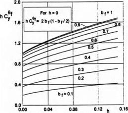
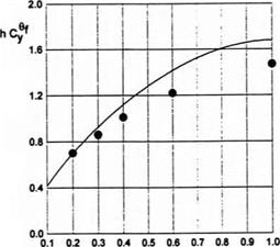
Parameter hCp versus ground clearance and the length of the flap is plotted in Fig. 3.3. In Fig. 3.4 a comparison is presented of the results of the present theory with calculated data of Shadrin [132] based on the method of the r-parameter.
|
Fig. 3.3. Parameter hC9y versus the relative ground clearance and the length of the flap, Л = oo. |
|
Fig. 3.4. Comparison of the calculated results for a flat plate of infinite aspect ratio, h=0.15. Solid line: MAE; circles: from [132]. |