Vortex Lift
Previous discussions regarding the effects of viscosity on the behavior of twodimensional airfoils and finite wings of conventional planform emphasized that operating these devices above moderate angles of attack results in flow separation at or near the leading edge, with a resulting catastrophic loss of lift. A delta wing with sharp leading edges, when operated at relatively small angles of attack, exhibits separated flow over the upper surface without a loss of lift until a very large angle of attack has been reached. This behavior is explained by the generation of vortex lift. Steady-flow vortex lift is discussed in this section.
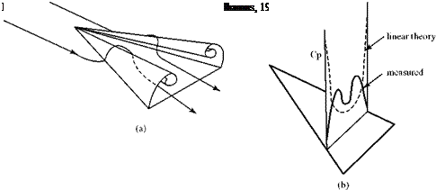
A delta-wing planform is attractive for supersonic flight because it has a small wave drag. However, it still must operate at subsonic speeds, particularly on takeoff and landing. If the delta wing has a sharp leading edge (desirable for supersonic flight), then at subsonic speeds and at small angles of attack, the flow separates at the leading edge and forms two large and dominant spiral vortices, shown in Fig. 6.28a with strong axial convection along the vortex core. These two spiral vortices alter the pressure distribution on the upper surface of the delta wing, causing a large suction pressure to be established on the wing surface almost directly beneath the centers of the spiral vortices, as shown in Fig. 6.28b.
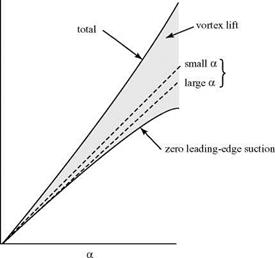
These large suction pressures on the wing upper surface furnish a so-called vortex lift, which at large angles of attack provides a significant increment to the potential flow (i. e., no separation) lift on the delta wing (Fig. 6.29). The spiral vortex


Figure 6.29. Behavior of delta wing at angle of attack. (Polhamus, 1966).
is sensitive to the geometry of the wing leading edge. For example, if the leading edge is rounded, the vortex-lift effect is reduced.
It is a challenging problem to model the details of the spiral vortices. However, a method was developed by Polhamus, 1966, which treats the vortices by an analogy and provides a surprisingly accurate prediction of the vortex lift and the associated drag due to lift. The analogy lies in the treatment of the leading-edge suction on a delta wing. Recall that leading-edge suction was introduced in the discussion of flat – plate airfoils in Chapter 5. When a near-zero-thickness airfoil is at an angle of attack, as shown in Fig. 6.30a, the flow upstream of the stagnation streamline reverses and flows around the sharp leading edge, causing a large suction as the streamline traverses a near-zero radius in inviscid flow. In a viscous fluid, the flow around the leading edge separates, as shown in Fig. 6.30b, and the streamlines upstream of the stagnation point behave as if they were flowing around a very blunt leading edge in an inviscid flow, as shown in Fig. 6.30c.
![]()
|
|
|
|


