Wall-Mounted Model for Application to Aileron Reversal
Before leaving the wind-tunnel-type models discussed so far in this chapter, we consider the problem of aileron reversal. “Aileron reversal” is the reversal of the aileron’s expected response due to structural deformation of the wing. For example, wing torsional flexibility can cause ailerons to gradually lose their effectiveness as dynamic pressure increases; beyond a certain dynamic pressure that we call the “reversal dynamic pressure,” they start to function in a manner that is opposite to their intended purpose. The primary danger posed by the loss of control effectiveness
![]()
|
is that the pilot cannot control the aircraft in the usual way. There are additional concerns for aircraft, the missions of which depend on their being highly maneuverable. For example, when control effectiveness is lost, the pilot may not be able to count on the aircraft’s ability to execute evasive maneuvers. This loss in control effectiveness and eventual reversal is the focus of this section.
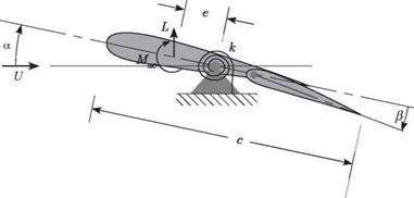
Consider the airfoil section of a flapped two-dimensional wing, shown in Fig. 4.10. Similar to the model discussed in Section 4.1.1, the wing is pivoted and restrained by a rotational spring with spring constant к. The main differences are that (1) a trailing – edge flap is added such that the flap angle в can be arbitrarily set by the flight-control system; and (2) we need not consider gravity to illustrate this phenomenon, so the weight is not shown in the figure. Moment equilibrium for this system about the pivot requires that
Mac + eL = кв (4.24)
The lift and pitching moment for a two-dimensional wing can be written as before; namely
![]() L = qSCL
L = qSCL
Mac = qcSCMac
When в = 0, the effective camber of the airfoil changes, inducing changes in both lift and pitching moment. For a linear theory, both a and в should be small angles, so that
![]() cl = CLaa + CLee
cl = CLaa + CLee
CMac = CMo + CM»e
where, as before, the angle of attack is a = ar + в. Note that CMe < 0; for convenience, we assume a symmetric airfoil (CM0 = 0).
Note that we may most directly determine the divergence dynamic pressure by writing the equilibrium equation without the inhomogeneous terms; that is
A nontrivial solution exists when the coefficient of в vanishes, yielding the divergence dynamic pressure as
![]() k
k
qD =
eSCLa
Clearly, the divergence dynamic pressure is unaffected by the aileron.
Conversely, the response is significantly affected by the aileron, as we now show. We can solve the response problem by substituting Eqs. (4.25) into the moment – equilibrium equation, Eq. (4.24), making use of Eqs. (4.26), and determining в to be
We see that because of the flexibility of the model in pitch (representative of torsional flexibility in a wing), в is a function of в .We then find the lift as follows:
1. Substitute Eq. (4.29) into a = ar + в to obtain a.
2. Substitute a into the first of Eqs. (4.26) to obtain the lift coefficient.
3.
Finally, substitute the lift coefficient into the first of Eqs. (4.25) to obtain an expression for the aeroelastic lift:
It is evident from the two terms in the coefficient of в in this expression that lift is a function of в in two counteracting ways. Ignoring the effect of the denominator, we see that the first term in the numerator that multiplies в is purely aerodynamic and leads to an increase in lift with в because of a change in the effective camber. The second term is aeroelastic. Recalling that CMe < 0, we see that as в is increased, the effective change in the camber also induces a nose-down pitching moment that— because the model is flexible in pitch—tends to decrease в and in turn decrease lift. At low speed, the purely aerodynamic increase in lift overpowers the aeroelastic tendency to decrease the lift, so that the lift indeed increases with в (and the aileron works as advertised). However, as dynamic pressure increases, the aeroelastic effect becomes stronger; there is a point at which the net rate of change of lift with respect to в vanishes so that
Thus, we find that the dynamic pressure at which the reversal occurs is
Notice that because CM, < 0, qR > 0. Obviously, a stiffer k gives a higher reversal speed, and a model that is rigid in pitch (analogous to a torsionally rigid wing) will
not undergo reversal. For dynamic pressures above qR (but still below the divergence dynamic pressure), a positive в will actually decrease the lift.
Now let us consider the effect of both numerator and denominator. As discussed previously, the divergence dynamic pressure also can be found by setting the denominator of L or в equal to zero, resulting in the same expression for qD as found in Eq. (4.27). Equations (4.27) and (4.32) can be used to simplify the expression for the lift in Eq. (4.30) to obtain
![]()
![]() qS[CLaar + CLe (1 – qR) в_
qS[CLaar + CLe (1 – qR) в_
1 – q
rd
It is clear from this expression that the coefficient of в can be positive, negative, or zero. Thus, a positive в could increase the lift, decrease the lift, or not change the lift at all. The aileron’s lift efficiency, n, can be thought of as the aeroelastic (i. e., actual) change in lift per unit change in в divided by the change in lift per unit change in в that would result were the model not flexible in pitch; that is
change in lift per unit change in в for elastic wing
n = ——————————————————–
change in lift per unit change in в for rigid wing
Using this, we can easily find that
1 – q
n = rrf (4.34)
qD
which implies that the wing will remain divergence-free and control efficiency will not be lost as long as q < qD < qR. Obviously, were the model rigid in pitch, both qD and qR would become infinite and n = 1.
Thinking unconventionally for the moment, let us allow the possibility of qR < qD. This will result in aileron reversal at a low speed, of course. Although the aileron now works opposite to the usual way at most operational speeds of the aircraft, this type of design should not be ruled out on these grounds alone. Active flight-control systems certainly can compensate for this. Moreover, we can obtain considerably more (negative) lift for positive в in this unusual regime than positive lift for positive в in the more conventional setting. This concept is a part of the design of the Kaman “servo-flap rotor,” the blades of which have trailing-edge flaps that flap up for increased lift. It also may have important implications for the design of highly maneuverable aircraft. Exactly what other potential advantages and disadvantages exist from following this strategy—particularly in this era of composite materials, smart structures, and active controls—is not presently known and is the subject of current research.
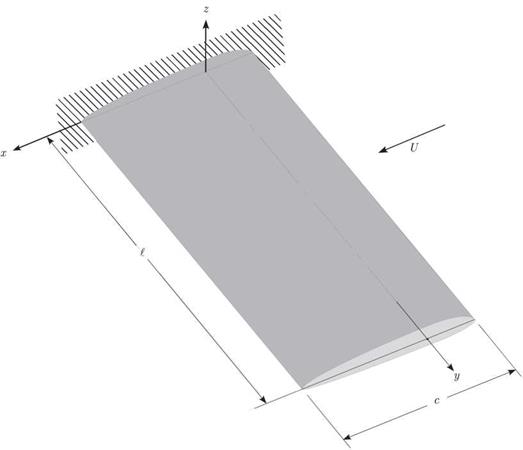
We revisit this problem in Section 4.2.5 from the point of view of a flexible beam model for the wing.
|
Figure 4.11. Uniform unswept clamped-free lifting surface |


