Balanced controls
Nowadays most larger aircraft have powered controls, but on smaller aircraft and older types, manual controls are still used. It is perhaps surprising to find that executive jets and even some small regional jet airliners retain manual controls. It should be remembered, however, that aircraft often remain in service for many decades, and quite recent models may only be updated variants of very old designs. The following description applies to manual controls, which are the type that student pilots will initially have to deal with.
Although, in general, the forces which the pilot has to exert in order to move the controls are small, the continuous movement required in bumpy weather becomes tiring during long flights, especially when the control surfaces are large and the speeds fairly high. For this reason controls are often balanced, or, more correctly, partially balanced (Fig. 9H).
Several methods have been employed for balancing control surfaces. Figure 9.13 shows what is perhaps the most simple kind of aerodynamic balance. The
hinge is set back so that the air striking the surface in front of the hinge causes a force which tends to make the control move over still farther; this partially balances the effect of the air which strikes the rear portion. This is effective but it must not be overdone; over-balancing is dangerous since it may remove all feel of the control from the pilot. It must be remembered that when the control surface is set a small angle, the centre of pressure on the surface is well forward of the centre of the area, and if at any angle the centre of pressure is in front of the hinge it will tend to take the control out of the pilot’s hands (or feet). Usually not more than one-fifth of the surface may be in front of the hinge.
|
|
Fig 9.13 Aerodynamic balance
|
|
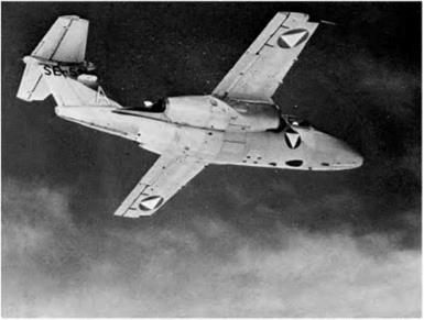
Fig 9H Balanced controls and tabs (By courtesy of SAAB, Sweden)
Twin-jet training aircraft showing the statically and aerodynamically balanced ailerons with geared servo-tabs; starboard tab adjustable for trimming. Elevators and rudder are also balanced, and there is a trim tab on the rudder, and a servo-tab (adjustable for trimming) on each elevator.
 |
|
![]()
 |
Force on
‘RIGHT’ servo rudder
RUDDER
Fig 9.16 Servo system of balance
Figures 9.14 and 9.15 show two practical applications of this type of balance; in each some part of the surface is in front of the hinge, and each has its advantages.
Figure 9.16 shows the servo type of balance which differs in principle since the pilot in this case only moves the small extra surface (in the opposite direction to normal), and, owing to the leverage, the force on the small surface helps to move the main control in the required direction. It is, in effect, a system of gearing.
Perhaps the chief interest in the servo system of balance is that it was the forerunner of the balancing tabs and trimming tabs. The development of these control tabs was very rapid and formed an interesting little bit of aviation history.
The servo system suffered from many defects, but it did show how powerful is the effect of a small surface used to deflect the air in the opposite direction to that in which it is desired to move the control surface.
The next step was to apply this idea to an aileron when a machine was inclined to fly with one wing lower than the other. A strip of flexible metal was attached to the trailing edge of the control surface and produced the necessary corrective bias.
So far, the deflection of the air was only in one direction and so we obtained a bias on the controls rather than a balancing system. The next step gave us both balance and bias; the strip of metal became a tab, i. e. an actual flap hinged to the control surface. This tab was connected by a link to a fixed surface (the tail plane, fin or main plane), the length of this link being adjustable on the ground. When the main control surface moved in one direction, the tab moved in the other and thus experienced a force which tended to help the main surface to move – hence the balance. By adjusting the link, the tab could be set to give an initial force in one direction or the other – hence the bias.
Sometimes a spring is inserted between the tab and the main control system. The spring may be used to modify the system in two possible ways –
1. So that the amount of tab movement decreases with speed, thus preventing the action being too violent at high speeds.
2. So that the tab does not operate at all until the main control surface has been moved through a certain angle, or until a certain control force is exerted.


