Our heavyweight helicopter equal in the world does not have
In Rostov started production of the most load-lifting rotary-wing car The Russian holding «Helicopt[...]

Everything about aircrafts and helicopters. News and events in aviation worldwide. Civil, transportation, military helicopters and airplanes.

Everything about aircrafts and helicopters. News and events in aviation worldwide. Civil, transportation, military helicopters and airplanes.

Everything about aircrafts and helicopters. News and events in aviation worldwide. Civil, transportation, military helicopters and airplanes.

Everything about aircrafts and helicopters. News and events in aviation worldwide. Civil, transportation, military helicopters and airplanes.


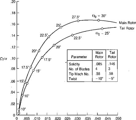
The hover charts starting on page 81 were prepared using the combined momentum and blade element method just described. The charts are based on the following assumptions: [2]
|
CqIg FIGURE 1.44 Calculated Performance of Isolated Main and Tail Rotors of Example Helicopter |
• NACA 0012 airfoil characteristics based on the whirl tower tests of reference 1.1. Thus the Reynolds number characteristics correspond to a 16-inch chord.
• Blade cutout = 0.15 R