LIFT OF SWEPT WINGS
Possibly the most dramatic single development in the aerodynamic design of aircraft is the invention, the exploration and the practical application of the swept wing, first in high-speed-comb at (1947) and then in commercial transport airplanes (1952). In this first chapter dealing with sweep, characteristics of wings are presented as follows: principles of swept wings, the lift of swept wings, influence of compressibility on lift. Some of the characteristics of wings already discussed in other chapters are found to be more complicated for swept wings.
usually defined as that of the quarter-chord line. As we will see later, this is one of the fallacies of theoretical aerodynamics, however. In figure 1, we have used the Vi chord line for the definition of sweep. It is interesting to note that when looking at a swept plan form, particularly as in part (c) of the illustration, one tends to overestimate its aspect ratio. The eye evidently sees the elongation of the two panels, and the “aspect ratio” of the panels is obviously what the structural engineer has to cope with.
1. PRINCIPLES OF SWEPT-WING FLOW
Swept wings have specifically been developed to increase the critical Mach number. Thus, higher cruise speeds are possible without encountering a high drag rise due to high operating Mach numbers. Further, since the critical Mach number decreases with increasing section thickness ratio and camber the effects of increasing these parameters, say for structural reasons, can be compensated for with an increase of the sweep angle.
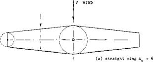
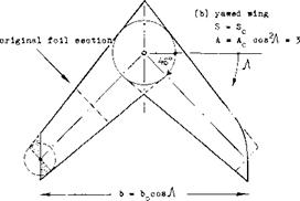
GEOMETRY. The elements of swept wings are the wing panels. As shown in figure 1 the simplest way of “producing” a swept wing is by sweeping (yawing) the two panels (as in variable-sweep airplanes). The wing sections are thus kept constant constant normal to each panel axis. The span and aspect ratio of such wings are reduced in the process:
b = bQ cosyt ; A = A0cosy (1)
where the subscript “o” refers to the unswept wing.
The tips of a “yawed” swept wing are usually modified to a “sheared” form, as shown in figure l, b. In reports such as (1) or (26,c, h) a leading edge curving back near the wing tips has been developed in England, evidently accommodating the trailing vortices which cannot very well be suppressed; see figure l, b. The angle of sweep Л is
|
|
|
|
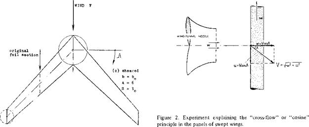
Figure 1. Geometry of swept wings; example of a tapered wing with Асд= 6, swept to Ac/4 =45°.
(1) Bagley, “Aerodynamic Principles of Swept Wings”, Vol 3 “Progress in Aeron Sciences”, Pergamon 1962.
SHEARED WING. A sheared wing is produced by moving (on paper) the wing sections parallel to one another in flow or flight direction until the desired angle of sweep is obtained. Since span and aspect ratio remain constant in this case, and the wing tips retain their lateral edges (as they are usually designed for airplanes) this definition seems to be preferable in analysis and discussion. It should be indicated, however, whether the foil sections are defined in the direction of flow (sheared) or normal to edges or axes of the wing panels (yawed). The thickness ratio is:
(t/c)v = (t/c)n cos J (2)
where V indicates the direction of flow or flight, and “n” that of the component w, that is “normal” to the edges or axes of the wing panels.
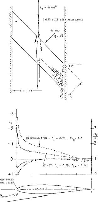
(w = V cos Л ) and (u = V sinA ) (4)
As long as skin friction is of little or no importance, (2,d) the u component does not have an influence upon the pressure forces (drag, lift, pitching moment, wing-flaps, compressibility) produced by the component w. In other words, we could calculate and/or measure for example lift:
L= CLaorn S(0.5 ^ w2 ) (5)
where C uo( = lift-curve slope in two-dimensional flow would be a constant characteristic of the airfoil section, such as (0.9 2 к ) — 0.01 , and defined in the direction of w that is normal to the edges of the wing. Referring this result to direction and magnitude of the “total” speed V, the dynamic pressure has to be modified corresponding to
(0.5 p wz )/q = (w/V)2 = cos A (6)
|
CROSS-FLOW PRINCIPLE. To understand the aerodynamic mechanism of sweep, we will consider a long and narrow piece of wing, similar to that in figure 2, moving across a stream of air ejected from the nozzle of an open-type wind tunnel. Evidently, the wing is subjected to the velocity w. However, since the wing itself is moving sideways with the velocity u, the resultant speed of air against the wing is the geometrical sum
V = Vw2 +u2 (3)
To say it in different words, the speed “V” (of a swept – wing airplane) can be split up into the components
In the new system, which corresponds to a straight wing flying at an angle of yaw (sideslipping), the angle of attack measured in the direction of V is reduced to
cos A (7)
In two-dimensional flow the lift is then
L = c L or s( «"n / °0 t(°-5 p w2 )/q] q (8)
and the coefficient, with subscript “2”, is for condition in the direction of flight
(2) Lift of airfoil sections in oblique flow:
a) Lippisch, Pressures in Oblique Flow, ZWB FB 1669 (1942), NACA TM 1115; also Koch ZWB UM 3006.
b) Dannenberg, Pressure Distribution, NACA TN 2160.
c) Watkins, Streamline Pattern, NACA TN 1231 (1947).
d) Cross-flow principle, III & XV of “Fluid Dyn Drag”.
C|_2 = ^La (tfp/cos-A )cos2A = CLcy<yz cosA
(9)
In other words, the lift-curve slope is (dCL /dec )2 =
(C L0C cos a) ; and the lift is L^cos A, for oc – constant in the direction of flow or flight.
YAWED AIRFOIL. Experimental results of a wing obliquely spanning the closed test section of a wind tunnel at an angle of 45 degrees are presented in figure 3.
|
Figure 3. Flow pattern and pressure distribution of an airfoil, tested (2,c) between tunnel walls, at an angle of yaw or sweep Ac/4 = 45°. The angle of attack is defined in the direction normal to the geometric span (axis) of the wings tested. |
Note that the panel is of the “yawed” type, and that c = constant (measured in the direction normal to the edges). The flow is essentially two-dimensional. As tested at half-span, pressure and lift coefficients are reduced in comparison to the same airfoil at Л = 0, in proportion to cos2y = 0.5; thus for a normal flow lift coefficient of 0.78 the effective value is: CL = 0.5 (0.78) = 0.39. It should be noted that the dashed line on figure 3 is drawn to Vi scale of the solid line, yet meeting most of the test points. However, if the angle of attack has been kept constant in the direction of flow (parallel to the tunnel walls) the lift and dC L /doc will be proportional to cos Л = 0.71, thus confirming equation (9). Based on the data presented in figure 3 the following observations are made:
a) Because of the presence of the tunnel walls the cross flow is not correct at both ends of the airfoil.
b) The forward end of the foil evidently pushes down some volume of air. A corresponding upwash (circulation across the stream) is thus induced ahea^ of the downstream area of the wing. As a consequence, lift in this end is some 10% higher, and in the upstream end 10% lower than in the center.
c) The boundary layer flows (at the higher lift coefficients) from the upstream end of the wing, picking up on its way roughly parallel to the trailing edge, finally arriving at the downstream end of the airfoil.
d) As a consequence of (b) and (c) stalling (separation) takes place first at the sweptback on downstream end. Maximum lift in the center sections of the two airfoils is reached approximately at the same angle ot, defined in tunnel direction. The coefficient is reduced, however, from CLx = 1.30, as in the airfoil at Л = 0, to 0.83. This value of C|_x is some 10% less than C Lx cos A = (1.3).71 = .923 which is the theoretical expectation.
e) If the downwind end of the wing fully produced the lift corresponding to the upwash stated under (b), the flow would be two-dimensional. Because of the boundary layer transport under (c), lift is deficient on the downwind side thus leading to part-stalling as under (d). As a consequence, the stream tube splitting “at”, the leading edge does not recombine past the trailing edge. This means that a certain rotation and/or circulation (a vortex) is left behind in the tunnel stream. This transfer of momentum results in an induced drag loss.
f) At CL =0 the wake-measured minimum drag coefficient is CD = 0.0041 for either of the two laminar – type airfoils tested. The CL size of the laminar “bucket” is reduced, however, by sweep, possibly in proportion to cos A. At су = 6 (in the direction of tunnel flow) C D = 0.0007 for either of the two angles of yaw tested; the lift coefficients are different, however.
Qualitatively, all components of the flow pattern properties discussed above are found in real swept wings!
DIRECTION OF FLOW. In spite of the cosine principle of “cross” flow, the average direction of the flow of air past the upper and lower sides of any swept wing is essentially that of the undisturbed outside flow. As a consequence, the Reynolds number (basically responsible for the development of the boundary layer) is properly defined using the average wing chord measured in that direction and the undisturbed velocity of flow or flight (3). It should also be noted that wing attachments such as engines, pylons supporting them, all kinds of fairings and the rails (tracks) supporting Fowler-type or multiple – slotted wing flaps, and finally fences (see later) are usually arranged in the same direction.
SIDESLIPPING. At an angle of yaw /3 , or when sideslipping, the lift of a straight wing changes in proportion to the effective dynamic pressure as in equation (6), and its sectional “lift angle” measured normal to the wing edges, increases accordingly. The induced angle is based on the wing span which is reduced in the direction of flow or flight in proportion to cos p. Consequently, (dop/dCL ) ^1/cos2# (where <yL is defined in the direction of flight), or (docni_ /dCL ) ~ l/cosz/3. Using the formulation as in Chapter II, the total angle (normal to the wing edges) is then approximately:
The fact that experimental results plotted in figure 4 more or less follow a simple cos2/3 function suggests that the first term in the equation deteriorates as a consequence of the boundary layer flow as stated under (c) above. It is seen, however, that an elliptical wing and one with zero taper ratio follow equation (10). In the case of a rectangular wing there is a secondary effect involved. When turning such a wing into an oblique flow, the span (measured between diagonally opposed corners) increases to a certain limit, particularly in small aspect ratios. As a consequence, the induced component of their lift angle may not increase within some range of the angle of yaw, such as 19°, for example, for A = 3. Our interest is, however, not in plain wings flying at an angle of yaw, and this may not be the best way of considering swept wings.


