PHYSICAL CONSIDERATIONS
The above mathematical formulation, even after selecting a desirable combination of sources and doublets, and after fulfilling the boundary conditions on the surface SB, is not unique. Previous examples showed that for describing the flow over thick bodies without lift the source distribution was sufficient, but for the lifting cases the amount of the circulation was not uniquely defined. Before proceeding further, (and using the information developed in Chapter 8), let us examine the case of a lifting wing, as viewed from a large distance (Fig. 9.2). For simplicity, the bound vortex is represented by a concentrated vortex line with the strength Г (= Г* = Гг). According to the Helmholtz theorems (Section 2.9) a vortex line cannot start in a fluid and following Eq. (4.64)
![]() ЗГ, = 5Г, dy dx
ЗГ, = 5Г, dy dx
which for the simple case of Fig. 9.2 implies that the problem is modeled by one, constant strength, closed vortex line. Also, the amount of the bound circulation is
Г = J q dl
where point 1 lies under and point 2 is above the (very) thin wake. These two arguments clearly demonstrate that for the three-dimensional lifting problem there is a need to model a wake, since the bound vorticity needs to be continued beyond the wing. Also, as shown in Fig. 9.2, in order for the wing to have circulation Г at a spanwise location (see Section 3.14), a discontinuity in the velocity potential near the trailing edge must exist:
Ф2 “ Фі = Г
where Ф] is under and Ф2 is above the wake. Now we are in a position where the additional physical conditions, required for a unique solution, can be
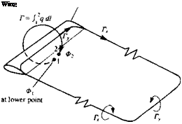 FIGURE 9.2
Vorticity system created by a finite wing in steady forward flight.
established in relation to a wake model. This model has to specify two additional conditions:
1. To set the wake strength at the trailing edge
2. To set its shape and location.
WAKE STRENGTH. The simplest solution to this problem is to apply the two-dimensional Kutta condition along the three-dimensional trailing edge (as shown in Fig. 9.3) such that
Уте. = 0 (914)
Since, for example, in the two-dimensional case d[i(x)/dx = – y(x) (as in Section 3.14) the above condition can be rewritten for the trailing edge line, such that ju is constant in the wake (nw) and equals the value at the trailing edge (mt. e.)
Mt. e. ~ = const.
Hu~ dw = 0 (9.15)
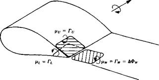
where (ifj and nL are the corresponding upper and lower surface doublet strengths at the trailing edge, as shown in Fig. 9.3. As an example, the specification of this Kutta condition in terms of constant-strength doublet elements (or vortex rings) is shown in Fig. 9.4 (here for convenience a positive doublet points into the wing). At the wing’s trailing edge, the trailing segment of the upper doublet will have a strength of – Гу, the leading vortex segment of the lower surface (which is now inverted) will be +TL and the leading segment of the wake vortex is +rw. Thus, the strength of the wake panel in terms of the local circulation Г is again
—Гу + TL + Г w = 0
or exactly as in Eq. (9.15),
rw = ry-rL (9.16)
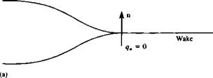
In certain situations also the shape of the trailing edge is important. For example, Fig. 9.5a shows a situation where the flow leaves the trailing edge
|
FIGURE 93 Implementation of the Kutta condition when using surface doublet distribution. |
|
Positive direction of Г
FIGURE 9.4 Implementation of the Kutta condition when using vortex ring elements. |
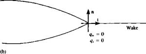
smoothly and parallel to the cusped trailing edge. In such situations this point is not necessarily a stagnation point and if the velocity formulation is used then only the qn= 0 condition can be used. In the case that the trailing edge has a finite angle (Fig. 9.5b), then in order to have a continuous velocity at this point the condition q, = 0 can also be used.
WAKE SHAPE. In two dimensions, the trailing vortex segment of the wake is not present and it is sufficient to specify the location of the trailing edge where the Kutta condition is met. In three dimensions, the wake influence is more
|
|
|
FIGURE 9.5 Possible conditions that can be applied at (a) cusp and (b) finite angle trailing edges. |
dominant and its geometry clearly affects the solution. To distinguish between the models for bound circulation (which generate the lift) and the circulation shed into the wake, it is logical to assume that the wake should not produce lift—since it is not a solid surface. As an example, let’s recall the formulation for the force AF generated by a vortex sheet with vorticity y. The Kutta – Joukowski theorem for lift (Section 3.11) states that
AF = pq X у (9.17)
For a three-dimensional case AF = 0 only if the local flow is parallel to у (we
assume у =£ 0). So the condition for the wake geometry is
qXyw=0 (9.18)
or the vorticity vector is parallel to the local velocity vector
Ywllq (9.18a)
An equivalent representation of the wake by a thin doublet sheet is obtained
by noting that yw = — (this will be demonstrated in Chapter 10). If no force is produced by this lifting surface then Eq. (9.18) becomes
Я x — 0 (9.19)
So the condition for the wake panels, in terms of doublets, is
jUw = const. (9.19a)
and the boundaries of these elements (which are really the vortex lines) should be parallel to the local streamlines, as in Eq. (9.18a). This condition (Eq. (9.18a)) is difficult to satisfy exactly since the wake location is not known in advance. In most cases it is sufficient to assume that the wake leaves the trailing edge at a median angle 6T E /2, as shown in Figs. 9.3 and 9.4, whereas
|
FIGURE 9.6 Effect of prescribed wake geometry on the aerodynamics of an Ж = 1.5 wing. |
for portions of the wake far from the trailing edge additional effort is required in order to satisfy the condition of Eq. (9.18).
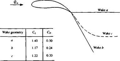
As an example of the dependence of the solution on the wake initial geometry, the results for a cambered rectangular wing of aspect ratio 1.5 are shown in Fig. 9.6. The solution was obtained by a first-order panel method (VSAERO9 2) with 600 panels per semispan and the corresponding lift and drag coefficents are tabulated in the inset to the figure (incidentally, case c is the closest to experimental results).


