SOME REMARKS ABOUT THE UNSTEADY KUTTA CONDITION
The potential flow examples, as presented in Chapters 3 and 4, indicate that the solution for lifting flows is not unique for a given set of boundary conditions. This difficulty was resolved by requiring that the flow leave smoothly at the trailing edge of two-dimensional airfoils thereby fixing the amount of circulation generated by the airfoil. The above two-dimensional Kutta condition was almost automatically extended to the three-dimensional steady-state case and in this chapter was used for unsteady flows as well. Although from the mathematical point of view a condition to fix the amount of circulation is required, it is not obvious that this condition is the best candidate. However, prior to arriving at any conclusion in this regard, let us use the method of this section to study the wake rollup behind a thin airfoil undergoing a small-amplitude heaving oscillation.
 |
FIGURE 13.28
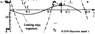
Variation of the vertical displacement and normal force coefficient during one heaving cycle. From Katz, J. and Weihs, D., “Behavior of Vortex Wakes from Oscillatory Airfoils”, Journal of Aircraft, Vol. 15, No. 12, 1978. Reprinted with permission. Copyright AIAA.
Consider the small-amplitude heaving oscillation of the flat plate shown in the inset to Fig. 13.28. Assume that the motion of the origin of the x, z coordinates is given by
Xa =~UJ X0 (f) = – t/„
Zq = ~ho sin (Ot Z0(0 = —h0a) cos Ш
0=0 0=0
The time-dependent kinematic velocity components of Eq. (13.116) then become
Since the normal vector to the flat plate is n = (0,1) the right-hand side (downwash) vector of Eq. (13.117) becomes
RHS, = ~(h0(o sin Ш + ww)
The wake-induced downwash is obtained by using Eq. (13.113) and then at each moment Eq. (13.118) is solved for the airfoil vortex distribution. The
 |
 |
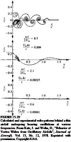
pressure difference is then obtained by using Eq. (13.127) and the wake rollup is obtained by moving the wake vortices with the local induced velocity (Eq. (13.132)). The rest of the details are as presented in the previous section and results of the wake rollup computation for the flat plate oscillating at various frequencies is shown in Fig. 13.29. The comparison in this figure indicates that up to a high reduced frequency of (oc/2Q„ = 8.5 the calculated wake shape is similar to the results of flow visualizations. Since the wake shape is a direct result of the airfoil’s circulation history and the calculated wake shape is similar to the experimentally observed shape, it is safe to assume that the calculated airfoil’s lift history is similar to the experimental one (which was not measured in this case). As an example, the vertical load Cz on the airfoil during one cycle is presented in Fig. 13.28 next to the motion history (note the phase shift due to the wake influence).
Now that we have generated a “good example” in favor of the unsteady Kutta condition, let us investigate some possible parameters affecting its validity. It is clear that conditions such as very high oscillation frequency, large amplitudes, and large angles of attack will cause some trailing edge separation. Such local flow separation automatically violates the Kutta condition, but in practice may not have a noticeable effect on the lift. On the other hand it may cause a lag in the aerodynamic loads. Experimental investigations of the unsteady Kutta condition13 7-1310 usually indicate that the streamlines do not leave parallel to the trailing edge at reduced frequencies of (Oc/2Q„>0.6, but the lift and pressure distributions are not affected in a visible manner even at higher frequencies. These experiments were based on small-amplitude oscillations of airfoils where the trailing-edge vertical displacement was small.
So, based on the indirect results of Fig. 13.29 and some cited references we can try to establish some guidelines for the boundaries for the validity of the unsteady Kutta condition. First and most important, large angles of attack where trailing edge separation begins to develop must be avoided. Also, it is clear that as the reduced frequency increases the “allowed” trailing edge displacement amplitude (e. g., h0 in the previous example) must be smaller. So, for example, with h0 = 0.1c and with reduced frequencies of up to (od2Qx = 1.0 calculations based on the Kutta condition may provide reasonable load calculations. The vertical kinematic velocity of the trailing edge (e. g., hJU,„ in the previous example) is an important parameter, too, and in the case of the highest frequency oscillation in Fig. 13.29 it has a value of about 0.35. So in addition to the previously mentioned limits on the reduced frequency and trailing-edge amplitude, if we limit ourselves to trailing-edge vertical displacement velocity of hJU. « 1, then for practical purposes we can assume that the unsteady Kutta condition is valid. Also, we must remember that characteristic airplane maneuvers will fall in a category where the reduced frequency is far less than 1, and therefore the use of the Kutta condition is justified in most cases. For a rapidly pitching helicopter rotor in forward flight this may not be the case!
The above discussion was aimed primarily at the lift calculation; however, the lag (due to viscous effects) in the adjustment of the flow at the trailing edge may cause some lags in the aerodynamic loads, and this effect is still not explored sufficiently.


