Some special designs
5.4 In this Section, we mention very briefly some special means which might be used in the design of swept wings to improve their characteristics. Most of these have not yet been exploited and applied in practice.
One possibility is to blow a thin jet out of a slot along the tip edge, as proposed, among others, by E Carafoli (1970). This will extend the tip vortex sheets (see Section 4.6) further out laterally and thus achieve an effectively larger span, which may have a beneficial effect on the vortex drag and also on the isobar pattern in the tip regions of a lifting wing. This scheme may be regarded as a "threedimensional jet flap". It has been proposed also for slender wings, with blowing from all edges; this will be discussed in Section
6.4.
Another possibility is to make the trailing edge blunt. This has been investigated extensively on twodimensional aerofoils (see e. g. J F Nash (1965),
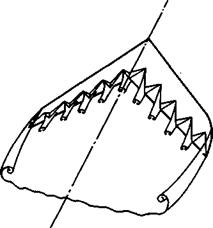
M Tanner (1973) and (1975)). The main beneficial effects can be expected to occur at transonic speeds in mixed flows: the slope of the rear upper surface can be reduced in this way, and the pressure to be reached at the trailing edge can be lower, because the flow can expand further around the base and reach the undisturbed mainstream pressure through a pressure rise downstream in the wake where the base separation bubble closes. In return, this must be paid for by a pressure drag on the base (more about base flows can be found in Section 5.9). Various means for reducing the base drag have been reviewed in detail by M Tanner (1975), including splitter plates, splitter wedges, serrated or segmented trailing edges, and base bleeds. Many of these have reached a promising state of development and may find useful practical applications, although it is not yet always clear how they might be combined with high-lift devices of variable geometry. The base drag may also be relieved by base burning, that is, by modifying the base flow by heat addition, as analysed by E G Broadbent (1973) (see also Section 5.9). Another possibility of reducing the base drag may be the incorporation of oonioal out-outs, as proposed by D KUchemann & J Reid (1960) and sketched in Fig. 5.26. Some parts
of the wing surface then retain the same low slope and pressure as on a wing with a blunt base. These parts end in a sharp vertical edge. Behind the apices of the cut-outs, the surface slopes down to a sharp horizontal trailing

|

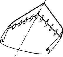
Fig. 5.26 Sketch of vortex sheets Fig. 5.27 Sketch of a sweptback wing shed from a wing with conical cut-outs with an array of bodies along the
trailing edge
edge, bounded on the sides by triangular vertical surfaces. If properly designed with a high enough angle of sweep, it can be expected that conical vortex sheets will be shed from the top edges of these vertical surfaces. The rolled-up cores of the sheets will induce a downward flow to fill the region over the cut-outs and, in this different flow mechanism, the boundary layer will not have to run up against a steep pressure gradient, as on conventional wings. But the rolled-up cores will also induce some suction over rearwardfacing surfaces and so there will be some drag penalty. The greater wing thickness provided by this scheme or by a blunt trailing edge should bring some structural benefits, and it should be possible to combine conventional high-lift devices with this scheme. However, very little is as yet known about how any of these devices work on threedimensional wings.
Under supercritical conditions, vortex flows as in Fig. 5.26 should make it impossible that strong rear shockwaves (such as (2) and (3) in Fig. 4.69) move towards the trailing edge and cause a rear separation with all its undesirable consequences (see Section 4.8). A similar effect may be achieved by a series of bodies, as sketched in Fig. 5.27. These may be put mainly on the upper surface; they may begin at or behind the maximum thickness or the crest and extend beyond the trailing edge. That the flow field induced by such a rear body should break up rear shockwaves and thus improve the buffet characteristics was suggested by D E Hartley (1953) and then applied to the fin-tailplane junction of the Hawker Hunter aircraft and successfully demonstrated in flight. That several bodies at the trailing edge of a wing, as in Fig, 5.27, can have a similar beneficial effect was demonstrated in flight in 1956 on the Gloster Javelin aircraft (see e. g. Anon (1958)). These "KUehemann carrots" are also known as "Whitcomb bodies", after R T Whitcomb who later made similar proposals. Although such bodies can be successful in improving the off-design behaviour of wings, they cannot necessarily be regarded as permanent features of properly-designed supercritical wings.
 |
Another design possibility again involves vortex flows. It concerns cranked wings and may be regarded as an alternative to the design concepts discussed above in connection with the Victor aircraft. As already stated, sweptback wings with large centre chords run counter to designs with uniform spanwise loading. If it is considered too difficult in a particular case to load up the centre part of a cranked wing, keeping the classical attached aerofoil flow, and if a thick inner wing is not wanted, the possibility might be considered of taking the serious step of giving up the concept of maintaining the same type of flow over the whole wing throughout the whole flight range. Instead, we think of combining two different types of flew on the same wing. We want to consider, as an example, the possibility of combining the classical aerofoil flow over part of the wing with the slender-wing flaw with coiled Vortex sheets above another part of the wing (see Section 3.3, Figs. 3.5 (b) and 3.6). We do not want to advocate its application but only speculate on what the properties of such "crossbreed" wings could be as compared with those of "pure" designs (see D Kuchemann (1971)). We are aware from the outset that such designs must be more risky and are more likely to fail.
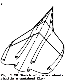
A simple way of thinking about the flow pattern is to take a typical sweptback wing of high aspect ratio and moderate angle of sweep, without fuselage. In the attached flow, the central kink effects extend about a half to one chord outwards from the centreline. Next, take a slender wing with sharp leading edges and an aspect ratio of about unity. The size of the slender wing could be such that the semispan is again between half and one chord of the swept wing. This slender wing is put in front of the swept wing to "cover the kink region", as it were, as sketched in Fig. 5.28. The combined flow past a lifting wing of this kind has coiled vortex sheets from the leading edges of the slender inner wing. These should then be cut at the crank where the two wings join in such a way that the entire sheets separate from the wing surface. Special means might have to be taken, if necessary, to bring this about. The vortex sheets from the slender part are then continued downstream as free vortex sheets. Each has two cores along the two free edges. The bound vortices on the slender part are then continued on the swept part behind. There are two possibilities: first, the bound vortices (which give circulation) could
be bent forward and linked across the centreline so that no trailing vortices with the wrong sign are shed from the combined wing. In this case, there may
even be a hump in the spanwise load distribution, leading to intensified local shedding of vorticity and the formation of double-branched cores, and a relatively large downwash in the middle region. This flow is sketched in Fig. 5.28. Second, the shape of the wing could be such that the bound vortex lines are not linked across the middle. This would lead to part-span shedding of vortices of the wrong sign and hence to relatively large drag forces due to lift. This should be avoidable by careful design. Also avoidable, but probably of minor importance, should be the cutting of the trailing vortex sheet by the intersection of the attachment lines with the trailing edge, because the outflow away from the attachment lines on the front part of the inner wing may become weaker over the rear part, and the attachment line may have disappeared in the trailing-edge region. In other words, the flow could be largely parallel to the freestream direction when it reaches the trailing edge. It ought to be possible, therefore, to design a combined wing to have a smooth flow which remains attached not only over the inner wing but also over the whole of the outer swept part of the wing.
With regard to the possible behaviour at low speeds, consider first the condition at high lift for the case without flaps. With the front wing, more lift should be generated in the middle part and the usual hole in the spanwise load distribution on conventional sweptback wings eliminated. To achieve this the non-linear lift resulting from the flow separation along the leading edge of this part of the wing would seem to be essential. (Attached flow over the inner wing would produce an even bigger hole in the spanwise (^-distribution) This improvement in the spanwise loading should imply that the tips can be unloaded, for a given value of the overall lift coefficient. Therefore, some improvement or delay with regard to tip stall, pitch-up, and wing drop may be expected. Even so, it seems probable that such wings would pitch up when they do stall, since the inner part of the wing is virtually "unstallable". In any case, the pitching-moment curve is not likely to be linear. Alternatively, the outer wing in the upwash field from the vortices of the inner wing could carry more lift, for a given angle of incidence. What really happens should be investigated on a complete model with tailplane because the large changes in downwash at the tail should also be taken into account, so that values of forces and moments can be obtained under trimmed conditions.
High-lift devices for the outer swept part of the wing can be designed largely in the usual way, especially leading-edge devices. Trailing-edge devices should be effective all along the span. Area increases needed may be smaller for the combined wing and could be tailored to better effect. It may be possible to reduce the angle of sweep of the trailing edge of the inner part of the wing, since this may not have quite such detrimental effects as on conventional sweptback wings.
The main disadvantage of the combined flow is the existence of free vortices quite close to the aircraft surfaces. There are no means of controlling the position of these free vortices, and induced yawing and rolling moments must be expected to be especially sensitive to the location of the free vortices relative to the fin. A high tail position may also lead to uncertain properties. To resolve these problems would require dynamic testing since static derivatives are not likely to reveal all the possible adverse effects.
With regard to the possible behaviour at high speeds, consider first the conditions in subcritioal flow. It is possible to design for an attached flow over the inner wing. The advantages would then lie in an improved isobar pattern, and camber and twist would have to be incorporated to achieve a high
local critical Mach number, combined with good lift production. But this can be done for only one specific design condition.
The other possibility is to make the leading edge sharp and to let the flow separate from the leading edges of the inner wing also at high speeds. This should again lead to a high local critical Mach number. As will be described in Section 6.3, the flow need not be conically supersonic anywhere even at an angle of incidence of about 20° and a freestream Mach number of 1.1 (see e. g.
J H В Smith & A G Kum (1968)). There is also the advantage of having a nearly parallel flow inboard of the attachment lines and especially near the centreline. Perturbation velocities can be expected to be small, therefore, and the inner wing should nevertheless show good lifting characteristics. However, the flow will go supercritical near the centreline in some conditions.
Consider now supercritical conditions. If the flow is kept attached along the leading edges of the inner wing, an isobar pattern similar to that in Fig.
5.1 (d) could be a worthwhile aim. If the flow is separated, the main advantage would be that there is no need for an inward flow behind the leading edges on the inner, conical, part of the combined wing. Hence there is no need for the front leg (1) in Fig. 4.69 of the shockwave pattern usually found on sweptback wings. There is still an inward flow over the swept and rounded parts of the leading edge. However, this does not meet a solid wall but vortex sheets instead. These may give way: there is a "soft" rather than a "stiff" interaction, in the manner of the flow element sketched in Fig. 2.13. The shockwave over the outer wings could be designed to be fully swept and then to fade out inboard. However, a relatively weak shock may be needed over the rear part of the inner wing. With such shocks present, there will be a largely unknown interaction between them and the free vortices; this could cause vortex breakdown (see e. g. E P Sutton (1955)). On the other hand, there could be a considerable relief on the outer swept part of the wing by loading up the middle region. Thus severe buffeting, wing rocking, and wing dropping could be delayed to higher lift coefficients or Mach numbers. Also. manoeuvre flaps could be very effective, especially trailing-edge flaps over the inner wing. Any such advantages may have to be paid for by an increase of the lift – dependent drag, as a result of the more complicated trailing-vortex system. A combined wing as in Fig. 5.28 is sometimes described as a sweptback wing with strokes. M Lotz (1974) has considered the design of supercritical wings with strakes in some detail. The possible improvements in manoeuvrability at high- subsonic speeds are seen as the main advantage of the central strakes, according to W Staudacher (1972).
A fuselage may be combined with such a wing without upsetting the desired flow characteristics. There is also the possibility of giving the front wing sufficient length and volume so that it may by itself form the front part of the fuselage.
Altogether, the advantages of combining two different types of flow on one wing all seem to stem from the elimination or the reduction of the kink effect near the centreline of a sweptback wing or near the body junction. This kink effect is replaced by a soft interaction at the joint between the two wing parts. We are not yet in a position to predict the flow in that region in any detail. A theory is not yet available and will be difficult to develop because the flow is essentially non-conical and non-slender in that region. If we want to find out what happens, a good experiment would seem to be the best way
We have been concerned here only with the reduction of the central kink effect hut it should he pointed out that one could think of a corresponding treatment of the tip regions of a swept wing. The sketch in Fig. 5.28 shows tip vortex sheets. These could result from deliberate design. A discontinuity may be introduced in the leading edge near the tip, say, one chord inboard from the tip or less. One could make the leading edge aerodynamically sharp outboard of that discontinuity and produce leading-edge vortex sheets there. Again, this would be a combination of vortex flows and attached flows. In fact, on such a wing, there would be flow separation along the inner part of the leading edge, followed by attached flow along the leading edge of the middle part of the wing, and separated flow again along the leading edge near the wing tips. All the flow separations would be fixed and controlled. Lift would be maintained over the tip region at low speeds as well as at high speeds, including supercritical conditions. Any pitch-up tendencies at the final stall might be reduced. Wings with mixed flow of this kind may, therefore, be worth further detailed investigation.
An alternative, and probably more meaningful, way of looking at mixed designs as in Fig. 5.28 is to regard them as yet another design condition of a variable-geometry aircraft, now for flight beyond the buffet boundary, where a conventional aircraft design will have an uncontrolled disorderly flow like that in Fig. 4.71 with several separations. The design objective would then be to fix the separation lines and to control the separated regions so as to arrive again at a well-behaved type of flow. We shall have to think about such multiflow wings much longer before we know well enough how to design them.


