Our heavyweight helicopter equal in the world does not have
In Rostov started production of the most load-lifting rotary-wing car The Russian holding «Helicopt[...]

Everything about aircrafts and helicopters. News and events in aviation worldwide. Civil, transportation, military helicopters and airplanes.

Everything about aircrafts and helicopters. News and events in aviation worldwide. Civil, transportation, military helicopters and airplanes.

Everything about aircrafts and helicopters. News and events in aviation worldwide. Civil, transportation, military helicopters and airplanes.

Everything about aircrafts and helicopters. News and events in aviation worldwide. Civil, transportation, military helicopters and airplanes.


Airfoil in curved flow So far, it had been assumed in all considerations of profile theory that the wing moves in straight incident flow. When investigating the interference of the airplane parts with each other, the case is encountered, however, where the wing lies in a curved incident flow field. The aerodynamic problems of such a wing can also be treated with the skeleton theory.
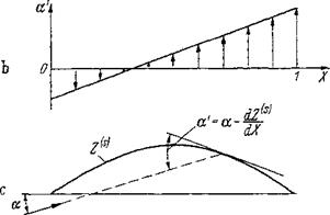
A flat plate in curved flow behaves approximately as a cambered skeleton in parallel flow. The variable angles of attack a(X) along a profile in curved flow can be replaced by changed equivalent skeleton line inclinations (a— dZ^jdX), as shown in Fig. 2-36. With this procedure in mind,
![]() = a —d{X)
= a —d{X)
must be substituted in the formulas of the skeleton theory (Sec. 24*2). By using the expressions of Table 2-1, the mean angle of attack a is obtained as
71
a = ~ j’^(f) (1 + oos<p)d<p (2-112fl)
о
This is, to express it again in a somewhat different way, the angle of attack that produces in straight flow the same lift cL = 27ra as the variable angle-of-attack distribution. The zero-moment coefficient becomes then
cj/o— —J/ «'(<p) (eosip-f cos2<p) dy (2-1126)
0
At a constant angle-of-attack distribution oc(X) = a, the above equations produce the relationships for the inclined plate: a = a, c^o — 0. Approximate expressions for a and cM0 have been derived by Pistolesi [45] and Multhopp (see Chap. 5 [40]), respectively. Using only local a values on a few characteristic stations of the chord, they arrived at the expressions
5 = OC.7S (2-113fl)
![]()
![]()
 L
L
a’
Figure 2-36 Airfoil in curved flow-schematic explanation, (л) Variation of a on plate. (b) Angle of incidence distribution a'(x). (c) Skeleton profile Z^s
|
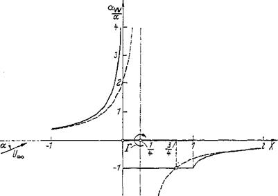
Figure 2-37 Distribution of the induced downwash angle on the extended wing chord for the inclined flat plate. |
C. V0 = (aoo ~b 2a50 — Зато) (2-1 ЪЬ)
where ol’qo, a5Q, a’7S, and a’10O mean the local angles of attack a at the stations X= 0, 0.5, 0.75, and 1.0, respectively. Hence, the value of the angle of incidence at the 4-chord station should determine the lift when the angle-of-incidence distribution is variable. Compare the formulas of Weissinger [73].
Theorem of Pistolesi The two approximation formulas of Pistol’esi and Multhopp are of particular importance when the continuously distributed circulation on the wing chord is replaced by a single vortex at the | – chord station, as is customary for simplified treatment of the wing of finite span (lifting-line theory, Sec. 3-3-4). The Pistolesi approximation for the mean angle of incidence is in agreement with the exact solution, as seen in Fig. 2-37. The Multhopp approximation for the zero moment produces the right value cMQ = 0 for the flat plate, because a[ю = —a50 and o4o = 3a’ltw when the plate is replaced by a single vortex at the | -chord station.
The velocity near-field of the profile So far, the velocity distributions have always been determined on the profile surface. For certain aerodynamic problems of airplanes, for example, for investigations into the influence of the wing on the incident flow of the fuselage or horizontal stabilizer, knowledge of the velocity field off the wing is required. This matter will now be discussed to some extent.
First, let the wing be replaced by its skeleton profile; that is, it is represented by its vortex distribution, Eq. (2-44). Of main interest are the z components w of the velocities because they produce a change of the effective angles of incidence on the airplane components that lie before and behind the wing. The induced velocity component w will be considered only in the wing plane, that is, on the ;c axis.
The distributions of the induced upwash and downwash velocities along the л axis are given by Eq. (246b):
і
mW=-T^I-T=lFdX’ (2-! 14)
o
Here k(x) is the circulation distribution along the profile chord and X=x/c, the dimensionless coordinate in direction of the profile chord. The total circulation of the wing Г is found from the circulation distribution by integration [see Eq. (2-52)]. Evaluation of Eq. (2-114) over the profile chord, 1, was described
earlier using the Birnbaum-Glauert substitution for the circulation distribution [Eqs. (2-61) and (2-63)].
Equation (2-114) can also be used to compute the induced downwash velocity before and behind the profile. A singular point of the integrand no longer exists in this case, however. The previous substitution of Eq. (2-62) now must be replaced by
X= £(1 ±cosh<y) (2-115a)
= + eosy’) (2-115b)
The lower sign applies to points before the wing and the upper sign to those behind the wing. By introducing Eqs. (2-115) and (2-61) into Eq. (2-114) and integrating, the downwash angle distribution aw = w/Uoo is obtained as
for X> andXCO[9]
In the circulation distribution Eq. (2-61), the term with A0 represents the flat plate inclined by the angle a, with A0 = a. The term with A1 represents the parabola skeleton with camber h/c in a flow parallel to the chord with A v =4h/c. For the first case, the distribution of the downwash angles along the profile chord is plotted in Fig. 2-37. For comparison is shown the induced downwash angle distribution that is obtained when the wing is substituted by a single vortex of total circulation Г, located in the center of action XA of the distributed circulation, that is, at XA = of the inclined plate. At large distances before and behind the wing, the distributions of the induced downwash angles of the continuous vortex distribution (lifting wing) and the single vortex (lifting line) are in agreement.
It is noteworthy that in the case of the inclined plate, the induced downwash velocities at station X = f are equal for the lifting surface and for the lifting line (Pistolesi theorem).
In the case of flow around thick profiles, the main interest is directed toward the induced velocity и in the x direction before and behind the profile. From Eq.
Figure 2-38 Distribution of induced longitudinal velocity on the extended wing chord for a symmetric Joukowsky profile (5 = t/c = thickness ratio).
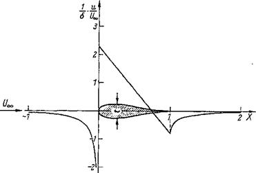 (2-91 a), this component is obtained by introducing the source distribution from Eq. (2-102). The evaluation is analogous to that of w(x) and produces for u(x)/U„ an equation analogous to Eq. (2-116), where the coefficients An of the circulation distribution must be replaced by ~Bn of the source distribution. The latter satisfy the closure condition Eq. (2-103). In Fig. 2-38, evaluation of such a computation is shown for a symmetric Joukowsky profile.
Although it is not possible in this book to cover the problems of unsteady flow that are of importance to airplane aerodynamics, the fundamental study of Wagner [72] on unsteady wing lift in plane flow should not be overlooked.