THE STEADY TURN
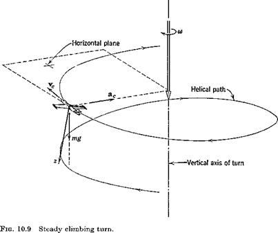
We define a “truly banked” turn to be one in which (i) the vehicle velocity vector to is constant and vertical (see Pig. 10.9) and (ii) the resultant of gravity and centrifugal force at the mass center lies in the plane of symmetry. This corresponds to flying the turn on the turn-and-bank indicator. f It is quite common for turns to be made at bank angles that are too large for
t Neglecting the fact that the pilot and indicator are not right at the C. G.

linearization of sin ф and cos ф to be acceptable, although all the state variables other than ф and F are small. Thus we turn to the basic nonlinear equations in Sec. 5.8 for this analysis. The large bank angle has the consequence that coupling of the lateral and longitudinal equations occurs, since more lift is needed to balance gravity than in level flight. Thus not only the aileron and rudder but the elevator as well must be used for turning at large ф.
The body-axis angular rates are given by
(10.4,4)
which for small elevation angle в yields
We now apply the second condition for a truly banked turn—that the ball shall be centered in the turn-and-bank indicator. This means that the vector mg — mac shall have no у component. But mac is the resultant external force f, so that from (5.5,3)
mg — ma, c = mg — f = —A
where A is the resultant aerodynamic force vector. Thus we conclude that the aerodynamic force must lie in the xz plane, and that У = 0. It follows from (5.8,26), when only ф and и are not small, that
mg sin ф = mru = mrV (10.4,6)
= mVco cos ф
Hence the bank angle is given by
tan ф = — (10.4,7)
g
We choose the body axes so that ctx = w = 0, whence it follows (see Fig. 4.4) that z and zw coincide, and hence that L = —Z. Equation (5.8,2c) then permits the determination of L, i. e.
L = —Z — mg cos в cos ф — m(pv — qu)
which, again to first order, after substituting q from (10.4,5) yields
L = mg cos ф + mVco sin ф (10.4,8)
When Fa) is eliminated by (10.4,7) we get
n = — = sec ф (10.4,9)
mg
The incremental lift coefficient, as compared with straight flight at the same speed and height, is
A CL = = (n~ 1 )GW (10.4,10)
ipv
We can now write down the equations governing the control angles. From
(5.8,3) , to first order, L = M = N = 0, so we have the five aerodynamic conditions
Ci = Cm = C„ = Cy = 0
(10.4,15) elevator angle per g in a turn is therefore not very different from that in a vertical pull-up.
Finally, the lateral control angles are obtained from the solution of (10.4,13)


