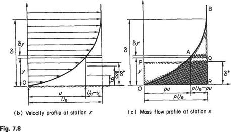
Various definitions of boundary-layer thickness
In the course of deriving the boundary-layer equations we have shown in Eqn (7.11) how the boundary-layer thickness varies with Reynolds number. This is another example of obtaining useful practical information from an equation without needing to solve it. Its practical use will be illustrated later in Example 7.1. Notwithstanding such practical applications, however, we have already seen that the boundary-layer thickness is rather an imprecise concept. It is difficult to give it a precise numerical value. In order to do so in Section 7.2.2 it was necessary, rather arbitrarily, to identify the edge of the boundary layer as corresponding to the point where и = 0.99f/e. Partly owing to this rather unsatisfactory vagueness, several more precise definitions of boundary-layer thickness are given below. As will become plain, each definition also has a useful and significant physical interpretation relating to boundary-layer characteristics.
Displacement thickness (8*)
Consider the flow past a flat plate (Fig. 7.8a). Owing to the build-up of the boundary layer on the plate surface a stream tube that, at the leading edge, is close to the surface will become entrained into the boundary layer. As a result the mass flow in the streamtube will decrease from pUe, in the main stream, to some value pu, and – to satisfy continuity – the tube cross-section will increase. In the two-dimensional flows considered here, this means that the widths, normal to the plate surface, of the boundary-layer stream tubes will increase, and stream tubes that are in the mainstream will be displaced slightly away from the surface. The effect on the mainstream flow will then be as if, with no boundary layer present, the solid surface had been displaced a small distance into the stream. The amount by which the surface would be displaced under such conditions is termed the boundary-layer displacement thickness (6*) and may be calculated as follows, provided the velocity profile u =f{y) (see Fig. 7.3) is known.
At station x (Fig. 7.8c), owing to the presence of the boundary layer, the mass flow rate is reduced by an amount equal to
|
|
corresponding to area OABR. This must equate to the mass flow rate deficiency that would occur at uniform density p and velocity Ue through the thickness 6*, corresponding to area OPQR. Equating these mass flow rate deficiencies gives
|
|
i. e.
|
|
|

The idea of displacement thickness has been put forward here on the basis of two-dimensional flow past a flat plate purely so that the concept may be considered in its simplest form. The above definition may be used for any incompressible twodimensional boundary layer without restriction and will also be largely true for boundary layers over three-dimensional bodies provided the curvature, in planes normal to the free-stream direction, is not large, i. e. the local radius of curvature should be much greater than the boundary-layer thickness. If the curvature is large a displacement thickness may still be defined but the form of Eqn (7.16) will be slightly modified. An example of the use of displacement thickness will be found later in this chapter (Examples 7.2 and 7.3).
Similar arguments to those given above will be used below to define other boundary-layer thicknesses, using either momentum flow rates or energy flow rates.
Momentum thickness (в)
This is defined in relation to the momentum flow rate within the boundary layer. This rate is less than that which would occur if no boundary layer existed, when the velocity in the vicinity of the surface, at the station considered, would be equal to the mainstream velocity Ue.
For the typical streamtube within the boundary layer (Fig. 7.8b) the rate of momentum defect (relative to mainstream) is pu{Ut — u)6y. Note that the mass flow rate pu actually within the stream tube must be used here, the momentum defect of this mass being the difference between its momentum based on mainstream velocity and its actual momentum at position x within the boundary layer.
The rate of momentum defect for the thickness в (the distance through which the surface would have to be displaced in order that, with no boundary layer, the total flow momentum at the station considered would be the same as that actually occurring) is given by pU&. Thus:
![]() pu(Ue – u)dy = pUB
pu(Ue – u)dy = pUB
i. e.
*-f£ (7Л7>
The momentum thickness concept is used in the calculation of skin friction losses.
Kinetic energy thickness (8**)
This quantity is defined with reference to kinetic energies of the fluid in a manner comparable with the momentum thickness. The rate of kinetic-energy defect within the boundary layer at any station x is given by the difference between the energy that the element would have at main-stream velocity t/e and that it actually has at velocity u, being equal to
![]() > і
> і
~pu(Ul – u*)dy /о L
while the rate of kinetic-energy defect in the thickness 6** is pU6**. Thus
П pu{Ul-f)&y = pUlsr Jo
i. e.


