
Our heavyweight helicopter equal in the world does not have
In Rostov started production of the most load-lifting rotary-wing car The Russian holding «Helicopt[...]

Everything about aircrafts and helicopters. News and events in aviation worldwide. Civil, transportation, military helicopters and airplanes.

Everything about aircrafts and helicopters. News and events in aviation worldwide. Civil, transportation, military helicopters and airplanes.

Everything about aircrafts and helicopters. News and events in aviation worldwide. Civil, transportation, military helicopters and airplanes.

Everything about aircrafts and helicopters. News and events in aviation worldwide. Civil, transportation, military helicopters and airplanes.


Consider another limiting case of a wing of small aspect ratio A <C 1. In this case, due to elongation of the wing in the direction of the flow, instead of a three-dimensional Laplace equation, a two-dimensional equation can be considered:
dV d2y
dy2 + dz2
For a wing with a slow increase in local span chordwise, it is sufficient to investigate a flow in a transverse plane passing through the trailing edge of the wing. Here it is convenient to render the problem nondimensional by a semispan //2 of the wing and speed U0 and introduce relative ground clearance, based on the span of the wing at the trailing edge h = h/l. For a flat wing, the corresponding velocity potential should satisfy the flow tangency condition on the wing and on the ground:
dp. . dp
Ty=-e• v=2h>’ <!=0′ »=°-
Following the general algorithm, one can demonstrate the main stages of the solution. For h <C A <C 1, the channel flow is described by the following relationships:
<pi = <Ph + %hm2 ln 2^ + + °(^i2)>
![]() d2p в ~d£ = 2h{
d2p в ~d£ = 2h{
In accordance with the general scheme, the potential of the upper flow pu is constructed by placing along the segment — 1 < x < 1 a distribution of sources with strength 6/h with the addition of admissible point sources at the points z = dil. These point sources model (in the upper flow) the leakage of air from beneath the wing around its edges. Then
<Pu = 2/ll^U! +0 (/if),
v"’=^in(i-22)-2bL>n{z~<)d<
= ^ІП^ “ 2^ ~ 2/^^ + ln^ + z) + (! – z) Ч1 – z) ~ 2]-
For a vanishingly thin and flat side edges, the structure of the edge potential remains the same as earlier:
Pe = 2haipae + 4/i12a2(£be + 4/г2а3г/ + 2ftia4,
where v — (z — l)/2h at the right tip and v = (—1 — z)/2h at the left tip of the wing.
Asymptotic matching of the velocity potentials y? i, and ipe leads to the following results
• Constants a, i
1 / в 7T
a3 = s(ai^slns;);
• Boundary conditions for the channel flow potential under the wing
¥>i(±l) = 2hi(a4 – ^)
Ws(±l) = ^ -0i(l + lnir) + A(2_ln2)
![]() For the problem of the leading order, в
For the problem of the leading order, в
![]() Ah
Ah
wherefrom it follows that in the extreme ground effect, the span – wise distribution of circulation for a wing of small aspect ratio is parabolic. It is easy to see that the corresponding downwash distribution is uniform. In accordance with Munk’s theorem, such a wing is optimal, i. e., has minimum induced drag for a given lift coefficient.
Including approximations of the order of 0(/ц), the following expression for the lift coefficient of a wing of small aspect ratio can be obtained:
To the leading order, the induced drag coefficient can be derived by using formula (2.109) in the form
![]() CXl
CXl
or in Prandtl’s representation,
|
X – l |
[___ і ^ |
||
|
h = o. os/* s |
|||
|
% = 0:07 |
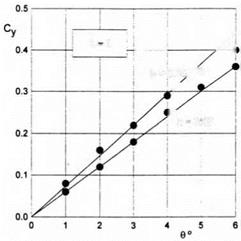
Fig. 3.5. Comparison of calculated results for a flat plate for different ground clearances with experimental data (Л — 1, solid lines: theory; circles: experiment).
Formulas (3.49) and (3.50) hold for a small-aspect-ratio wing of arbitrary planform.[13] Turning to a rectangular wing l = A, h = h = h/A, one can derive from (3.49), (3.50) that
|
ex |
f 6h , 7Г ‘ |
/ 6h |
7tA |
(3.51) |
|
|
: 6ЛІ1 |
(1 + ^>аГ. |
)=6Ґ |
(1 + ^ЛІП |
-)■ |
|
|
a2 |
A |
||||
|
cXl = |
II |
37Г /і’ |
Ae = A/z, |
(3.52) |
where h is the relative ground clearance based on the root chord, and Ae is the effective aspect ratio of the wing. Figure 3.5 presents a comparison of calculated results for A = 1, obtained by (3.51), with experimental results of Ermolenko et al. [133].
Within the assumption of a small aspect ratio, it is easy to consider the steady flow problem for a wing with curvilinear lateral curvature. Let the gap distribution be described as
/і*(ж, z) = 2hH(z) + to,
where h is the ground clearance based on the span, в is a pitch angle, and H(z) is a function of the order of 0(1) characterizing the form of the wing in the lateral direction, H(0) = 1. In this case, the linearization of (2.22) results in the following channel flow equation for a small-aspect-ratio wing with a curvilinear lateral axis:
This equation should be solved with boundary conditions
In the general case of a wing with a nonzero angle of heel ai(l) ф ni(—1)
ai(±l) = -^(±1)-
The potential of the upper flow ipu for a wing with a curvilinear lateral axis has the form
<pn ~ 2h(f>ni,
<Au = —oi(l) ln(l – z) + —ai(—1) ln(l + z)
7Г 7Г
|
C2dC tf(0’ |
|
C3dC H«Y |
 |
To the leading order, the expressions for the coefficients of the lift and lateral moment of wings of a small aspect ratio with a curvilinear lateral axis
Taking into account that, to the leading order, the lift coefficient of a flat plate of small aspect ratio is equal to Cyip = 9X/6h, we obtain the following formula, which allows estimating the relative influence of the lateral curvature of a wing in the ground effect
Consider some simple lateral forms of the lifting surface. Lateral configuration in the form of a “hat” is described by the function
H1(z) = l-(l-j^)z, г Є [-1,1].
In addition, we introduce parabolic and elliptic lateral configurations, represented, respectively, by the functions
-t+(* ■- £)^ w -£+ (‘ – £) ■
 |
Fig. 3.7. Relative lateral moment coefficient versus heel angle for small-aspect-ratio wings with different spanwise configurations (1: “hat;” 2 : parabolic; 3: elliptic).
Figure 3.6 illustrates the relative influence of the lateral curvature of the wing upon its lift coefficient for different magnitudes of the gap between the tips and the ground plane. Figure 3.7 shows the relative influence of the angle of heel upon the lateral moment coefficient mx for small-aspect-
ratio wings of different spanwise configurations. This parameter characterizes the static lateral stability of the wing, i. e., the capacity to restore its upright position after the action of heeling perturbations. Note that Fig. 3.7 compares the behavior of the ratio of the lateral moment coefficient mx for a given configuration to that of a flat plate mXfp versus heel angle /3.
The induced drag coefficient for a wing with a curvilinear lateral axis can be found by using (2.109) in the form
