Aileron Reversal
In Section 4.1.4, an example illustrating aileron reversal is presented based on a rigid, two-dimensional wing with a flexible support. In this section, we examine the same physical phenomenon using a torsionally flexible wing model. With the geometry and boundary conditions of the uniform, torsionally flexible lifting surface as before, we can derive the reversal dynamic pressure for a clamped-free wing. Two logical choices are presented regarding the defining condition. One is to define reversal dynamic pressure as that dynamic pressure at which the change of total lift with respect to the aileron deflection is equal to zero. Another equally valid definition is to define it as the dynamic pressure at which the change in root-bending moment with respect to the aileron deflection is equal to zero. Finally, we look at the effectiveness of ailerons for roll control—often termed the “roll effectiveness”—of a simplified flying aircraft model.
Note that the presence of an aileron requires that we modify the sectional lift and pitching moment coefficients, so that
![]() ci = aa + сівв cmac = сшрв
ci = aa + сівв cmac = сшрв
Using these coefficients and setting ar equal to zero, the sectional lift and pitching moment are given by
![]() L = qc (ав + сів M = eL + qc2cm/)P
L = qc (ав + сів M = eL + qc2cm/)P
where we assume that the aileron extends along the entire length of the wing. Assuming the weight to have a negligible effect on the reversal condition, the modified version of Eq. (4.49) is written as
— + х2в = – X2fp (4.74)
dy2
We may refine the theoretical result by considering a simplified correction from three-dimensional effects by use of a tip-loss factor, typically chosen as B = 0.97. Instead of obtaining the total lift by integrating the sectional lift over the entire wing length from y = 0 to y = £, we integrate only from y = 0 to y = B£.
|
d[6]e1 dy2 d292 dy2 d% dy2 |
|
+ Х2в1 = 0 + Х2в2 = – + Х2в3 = 0 |
|
Х2фв r£ < y < R£ |
Similarly, we may account for an aileron that does not extend over the entire length of the wing. Suppose that the aileron starts at y = r £ and extends to y = R£ with 0 < r < R < 1. This means that there are as many as three segments to be analyzed. There is no inhomogeneous term for the segments between y = r£ and y = R£, so instead of Eq. (4.74), we write
and obtain the resulting six arbitrary constants by imposing the six boundary conditions
01(0) = 0 0l(r l) = в2(г l)
d01 , , d02, .
d7(r l) = d7(r l)
![]()
02( Rl) = 03( Rl)
Calculation of the reversal dynamic pressure from the second definition (i. e., the one in terms of the root-bending-moment criterion) is left as an exercise for readers (see Problem 20).
This treatment can be generalized easily to consider the roll effectiveness of a complete aircraft model. Similar problems can be posed in the framework of dynamics, in which the objective is, say, to predict the angular acceleration caused by deflection of a control surface, or the time to change the orientation of the aircraft from one roll angle to another. Depending on the aircraft and the maneuver, it may be necessary to consider nonlinearities. Here, however, only a static, linear treatment is included.
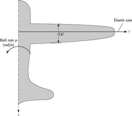
Consider a rolling aircraft with unswept wings, the right half of which is shown in Fig. 4.16, with a constant roll rate denoted by p. As shown in Fig. 4.17, the wing section has an incidence angle with respect to the freestream velocity of ar + 0 (y). In a roll maneuver with p > 0, the right wing moves upward while the left wing moves downward. The right wing then “sees” an additional component of wind velocity equal to py perpendicular to the freestream velocity and downward. As shown in Fig. 4.17, because py < U, the angle of attack is reduced from the incidence angle to ar + 0 – py/U.
Some contributions to the lift and pitching moment are the same (opposite) on both sides of the aircraft; these are referred to as symmetric (antisymmetric) components. Separate problems can be posed in terms of symmetric and antisymmetric parts, which are generally uncoupled from one another. In particular, we can treat the roll problem as an antisymmetric problem noting that all symmetric components cancel out in pure roll. Hence, we can discard them a priori. For example, in the relationship
a = af+ 0 (y) – U (4.83)
the first term, ar, drops out because of symmetry. Both 0 (y) and the roll-rate term are antisymmetric because 0 and в have the opposite sense across the mid-plane of the aircraft. The last term, which represents the increment in the angle of attack from
|
Figure 4.16. Schematic of a rolling aircraft |
the roll rate p based on the assumption of a small angle of attack, also is explicitly antisymmetric.
Assuming c(y) to be a constant, c, we may write the governing differential equation as
|2 + Х2в = X2 (U – e) (4.84)
with boundary conditions в (0) = de/dy(l) = 0. The solution is given by
в = P[Xy – sec(X£) sin(Xy)] + ffi[tan(Xl) sin(Xy) + cos(Xy) – 1] (4.85)
|
Figure 4.17. Section of right wing with positive aileron deflection |
 |
C)
Now, because the aircraft is in a steady-state rolling motion, the total rolling moment must be equal to zero. Thus, ignoring the offset of the wing root from the mid-plane of the aircraft, we may find the moment of the lift about the mid-plane of the aircraft
as
which, when set equal to zero, can be solved for the constant roll rate p. (Note that the three terms in Eq. [4.86] are the contributions toward the rolling moment due to the elastic twist, the roll rate p, and the aileron deflection в, respectively.) This result, written here in dimensionless form as pt/U, is given by
pt _ kt [ccmf) [(kt)2 – 2sec(kt) + 2] – 2ectp [sec(kt) – 1]} в 87)
U 2ae[kt — tan(kt)] .
which is proportional to в. At a certain dynamic pressure, we are unable to change the roll rate by changing в. This dynamic pressure occurs when the sensitivity of the roll rate to в vanishes; viz.
9 (U) kt {ccmв [(kt)2 — 2 sec(kt) + 2] — 2ect^ [sec(kt) — 1] } 0
дв 2ae[kt — tan(kt)] ( . )
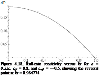
For specific values of e/c and the sectional airfoil coefficients ctf and cmf), we may numerically solve this equation for a set of roots for kt. The lowest value is associated the aileron reversal. Alternatively, we simply may plot the quantity in Eq. (4.88) versus kt until it changes sign, which is the reversal point.
For a specific case (i. e., e = 0.25c, ctв = 0.8, and cmв = -0.5), the roll-rate sensitivity is shown versus kt, which is proportional to the speed U, in Fig. 4.18, which shows the reversal point at kt = 0.984774. Notice that the curve at low speed starts
as relatively flat and monotonically decreases until the reversal point is reached. This shape is a typical result and shows the importance of static aeroelasticity in this aspect of flight mechanics. It is also interesting to observe the relative contributions to the rolling moment from the elastic twist, the rolling motion, and the aileron deflections depicted in Fig. 4.19. At the reversal point, p vanishes, and the rolling moment contributions from elastic twist and from aileron deflection exactly cancel out one another.


