Axis Systems
The orientation of the axis system used to quantify any vector or tensor is arbitrary. Common choices are to align one axis (e. g. the x axis) with either a body feature such as an airfoil chordline, or with the freestream direction. If the body is only translating, a common axis system can be used for all quantities. However, if the body is rotating, then two axis systems naturally arise:
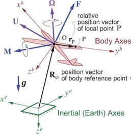
• “Earth” axes xe, ye, ze fixed to the ground. These are non-rotating (the Earth’s rotation is neglected).
• “Body” axes xb, yb, zb fixed to the body. These rotate along with the body relative to inertial space.
Note that “frame” and “axes” are distinct concepts. For example, the aircraft position, velocity, and rotation rate Ro, U, О treated in Chapter 7 were all defined in the Earth frame. But Ro is usually expressed via its Earth-axes xe, ye, ze components, while U, О are usually expressed via the aircraft’s body-axes xb, yb, zb components. Relating them requires the axis transformation relations developed in Appendix F.
9.2 Body Position and Rate Parameters
Application of the equations of fluid motion in unsteady or quasi-steady flow situations requires specification of the velocity of every point on the body surface. This is parameterized by the inertial-frame quantities,
U(t) velocity vector of body reference point O O(t) rotation-rate vector of body
so that a point P at some location rp on the body relative to point O has the following velocity.
Up = U + Ox rp
In aircraft flight dynamics applications the atmosphere is occasionally specified to have some nonuniform “gust” velocity field VgUst(R, t), whose effect on the forces on the aircraft is to be determined. To evaluate this gust velocity at each point rp on the aircraft requires knowing that point’s Earth position within the gust field. This is parameterized by
Ro(t) position of body reference point O
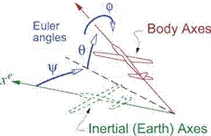
ф, в, ф(р body roll, elevation, and heading Euler angles
which are sketched in Figure 9.2. The Earth position of point P and the gust velocity at that point can then be obtained from the VgUst(R, t) field.
Rp(r, t) R0(t) + rp (9.1)
 |
 |
(Vgust )p = Vgust(Rp >t) (9.2)
Figure 9.2: Aircraft motion parameters. Total aerodynamic force F and moment M are also shown.
= e = b
Euler angles define transformation matrices Tь or Te between body and Earth axes, developed in Appendix F.


