Sweep Effects
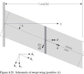
To observe the effect of sweeping a wing aft or forward on the aeroelastic characteristics, it is presumed that the swept geometry is obtained by rotating the surface about the root of the elastic axis, as illustrated in Fig. 4.20. The aerodynamic reactions depend on the angle of attack as measured in the streamwise direction as
a = ar + в (4.89)
where в is the change in the streamwise angle of attack caused by elastic deformation. To develop a kinematical relationship for в, we introduce the unit vectors a1 and a2, aligned with the y axis and the freestream, respectively. Another set of unit vectors, b1 and b2, is obtained by rotating a1 and a2 by the sweep angle Л, as shown in Fig. 4.20, so that b1 is aligned with the elastic axis (i. e., the y axis). From Fig. 4.20, we see that
![]()
 |
b1 = cos^^ + sin^)a2 b2 =- sin^^ + cos^)a2
Observe that the total rotation of the local wing cross-sectional frame caused by elastic deformation can be written as the combination of rotations caused by wing
torsion, в about bi, and wing bending, dw/dy about b2, where w is the bending deflection (positive up, which in Fig. 4.20 is out of the paper). Now, в is the component of this total rotation about jq; that is
![]() dw ■ . л
dw ■ . л
в bi + — b2 ) ■ ai
![]()
 |
 |
в cos(A) – ddWW sin(A)
From this relationship, it can be noted that as the result of sweep, the effective angle of attack is altered by bending. This coupling between bending and torsion affects both the static aeroelastic response of the wing in flight as well as the conditions under which divergence occurs. Also, it can be observed that for combined bending and torsion of a swept, elastic wing, the section in the direction of the streamwise airflow exhibits a change in camber—a higher-order effect that is here neglected.
To facilitate direct comparison with the previous unswept results, to the extent possible, the same structural and aerodynamic notation is retained as was used for the unswept planform. To determine the total elastic deflection, two equilibrium equations are required: one for torsional moment equilibrium as in the unswept case and one for transverse force equilibrium (associated with bending). These equations can be written as
In these equilibrium equations, a is used to denote the two-dimensional lift-curve slope of the swept surface and cmac to represent the two-dimensional pitching- moment coefficient of the swept surface. These aerodynamic constants are related to their unswept counterparts by
![]() a = a cos(A)
a = a cos(A)
cmac = cmac cos (A)
for moderate – to high-aspect-ratio surfaces. Substituting for a, a = ar + в and, in turn, the dependence of в on в and w from Eq. (4.91), specializing for spanwise uniformity so that GJ and EI are constants, and letting ()’ denote d()/dy, we obtain two coupled, ordinary differential equations for torsion and bending given by
в a + q^ в cos2(A) – qffw’ sin(A)cos(A)
1
= -^= [qecaar cos(A) + qc2cmac cos2(A) – Nmgd]
GJ
w"" + =w’ sin(A) cos(A) – qcaв cos2(A) = = [qcaar cos(A) – Nmg] (4.94)
EI EI EI
Because the surface is built in at the root and free at the tip, the following boundary conditions must be imposed on the solution:
|
y = 0: |
в |
=0 |
(zero torsional rotation) |
|
|
w |
=0 |
(zero deflection) |
||
|
y = t: |
w’ в’ |
=0 =0 |
(zero bending slope) (zero twisting moment) |
(4.95) |
|
w" |
=0 |
(zero bending moment) |
||
|
w"’ |
‘ = 0 |
(zero shear force) |
Bending-torsion coupling is exhibited in Eqs. (4.94) through the term involving w in the torsion equation and through the term involving в in the bending equation.
There are two special cases of interest in which the coupling either vanishes or is much simplified so that we can solve the equations analytically. The first is for the case of vanishing sweep in which the uncoupled torsion equation (i. e., the first of Eqs. [4.94]) is the same as previously discussed and clearly leads to solutions for either the torsional divergence condition or the torsional deformation and airload distribution as discussed (see Sections 4.2.3 and 4.2.4, respectively). In the latter case, once the torsional deformation is obtained, the solution for в = в can be substituted into the bending equation (i. e., the second of Eqs. [4.94]). Integration of the resulting ordinary differential equation and application of the boundary conditions lead to the shear force, bending moment, bending slope, and bending deflection.
A second special case occurs when e = 0. In this case, torsional divergence does not take place, and a polynomial solution for в can be found from the в equation and boundary conditions. Substitution of this solution into the bending equation leads
to a fourth-order, ordinary differential equation for w with a polynomial forcing function; note that the в terms are now part of that forcing function. This equation and accompanying boundary conditions can be solved for the bending deflection, but the solution is not straightforward. Alternatively, to solve this equation for a divergence condition, we need only the homogeneous part, which can be written as a third-order equation in Z = w’; namely
ZZ sin(A) cos(A) = 0 (4.96)
EI
For the clamped-free boundary conditions Z (0) = Z ‘(0 = Z"CO = 0, this equation has a known analytical solution that yields a divergence dynamic pressure of
![]()
 |
, — (4.97)
acl3 sin(A) cos(A)
The minus sign implies that this bending-divergence instability takes place only for forward-swept wings; that is, where A < 0.
Examination of Eqs. (4.94) illustrates that there are two ways in which the sweep influences the aeroelastic behavior. One way is the loss of aerodynamic effectiveness, as exhibited by the change in the second term of the torsion equations from
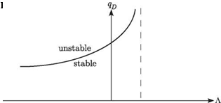
Note that this effect is independent of the direction of sweep. The second effect is the influence of bending slope on the effective angle of attack (see Eq. 4.91), which leads to bending-torsion coupling. This coupling has a strong influence on both divergence and load distribution. The total effect of sweep depends strongly on whether the surface is swept backward or forward. This can be illustrated by its influence on the divergence dynamic pressure, qD, as shown in Fig. 4.21. It is apparent that forward sweep causes the surface to be more susceptible to divergence, whereas backward sweep increases the divergence dynamic pressure. Indeed, a small amount of backward sweep (i. e., for the idealized case under consideration, depending on ell and GJ/ EI, only 5 or 10 degrees) can cause the divergence dynamic pressure to become sufficiently large that it ceases to be an issue. Specific cases are discussed later in this section in conjunction with an approximate solution of the governing equations.
Figure 4.22. Lift distribution for positive, zero, and negative A
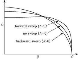 The overall effect of sweep on the aeroelastic-load distribution also strongly depends on whether the surface is swept forward or backward. This is illustrated in Fig. 4.22, which shows spanwise load distributions for an elastic surface for which the total lift (or N) is held constant by adjusting ar. From the standpoint of structural loads, it is apparent that the root bending moment is significantly greater for forward sweep than for backward sweep at a given value of total lift.
The primary motivation for sweeping a lifting surface is to improve the vehicle performance through drag reduction, although some loss in lifting capability may be experienced. However, these aeroelastic considerations can have a significant impact on design decisions. From an aeroelastic standpoint, forward sweep exacerbates divergence instability and increases structural loads, whereas backward sweep can alleviate these concerns. The advent of composite lifting surfaces enabled the use of bending-twist elastic coupling to passively stabilize forward sweep, making it possible to use forward-swept wings. Indeed, the X-29 could not have been flown without a means to stabilize the wings against divergence. We discuss this further in Section 4.2.7.
Exact Solution for Bending-Torsion Divergence. Extraction of the analytical solution of the set of coupled, ordinary differential equations in Eqs. (4.94) is complicated. The exact analytical solution is obtained most easily by first converting the coupled set of equations into a single equation governing the elastic component of the angle of attack. For calculation of only the divergence dynamic pressure, we can consider just the homogeneous parts of Eqs. (4.94):
![]() в" + qecaв cos2(A) – qecaw’ sin(A) cos(A) = 0 GJ GJ
в" + qecaв cos2(A) – qecaw’ sin(A) cos(A) = 0 GJ GJ
,,,, qca qca 2„
w + w sin(A) cos(A) – в cos2(A) = 0
EI EI
To obtain a single equation, we differentiate the first equation with respect to y and multiply it by cos(A). From this modified first equation, we subtract sin(A) times the
second equation, replacing в cos(A) – w’ sin(A) with в, to obtain
в+ q=a cos2(A)e7 + sin(A) cos(A)e = 0 (4.100)
Introducing a dimensionless axial coordinate n = y/t, this is equation can be written as
в+ qead cos2(A)e’ + sin(A) cos(A)e = 0 (4.101)
GJ EI
where () now denotes d()/dn. The boundary conditions can be derived from Eqs. (4.95) as
в(0) = в'(1) = в"(1) + qqeecaL. cos2(A)e (1) = 0 (4.102)
GJ
Here, the first of Eqs. (4.99) and the final boundary condition from Eqs. (4.95) are used to derive the third boundary condition.
The exact solution for Eqs. (4.101) and (4.102) was obtained by Diederich and Budiansky (1948). Its behavior is complex, with multiple branches, and it is not used easily in a design context. However, a simple approximation of one branch is presented next and compared with plots of the exact solution.
then, as shown by Diederich and Budiansky (1948), the divergence boundary can be approximately represented within a certain range in terms of a straight line
n 2 3n 2
тя = T + 1ъ в° (4.104)
2
Note that for a wing rigid in bending, we have во = 0 and, thus, td = Пр which is the exact solution for pure torsional divergence. Also, for a torsionally rigid wing, we have td = 0 and, thus, eD = -19/3, which is very close to -6.3297, the exact solution for bending divergence. For the cases in between, the error is quite small.
It is important to note that the sign of т is driven by the sign of e, whereas the sign of в is driven by the sign of Л. The approximate solution in Eq. (4.104) is plotted along with some branches of the exact solution in Fig. 4.23. Note the excellent agreement between the straight-line approximation and the exact solution near the origin. Note also that the intersections of the solution with the td axis (where во = 0) coincide with the squares of the roots previously obtained in Section 4.2.3, Eq. (4.63), as (2n – 1)2n 2/4 for n = 1, 2,…, ж (i. e., n 2/4, 9n 2/4,…).
A more convenient way of depicting the behavior of the divergence dynamic pressure is to plot тD versus a parameter that depends on only the configuration. This can be accomplished by introducing the dimensionless parameter r, given by
 в t GJ
r = = tanm
т e EI
which can be positive, negative, or zero. Equation (4.104) can then be written as
 |
|
Thus, we can solve for td such that
Several branches of the exact solution of Eqs. (4.101) and (4.102) for the smallest absolute values of td versus r are plotted as solid lines in Fig. 4.24. Note that there is
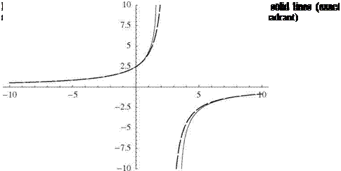 |
at least one branch in all quadrants except the third, and there is only one branch in the fourth quadrant. The approximate solutions for td versus r from Eq. (4.107) are plotted as dashed hyperbolae in the first, second, and fourth quadrants. Moreover, as r becomes large, the solution in the fourth quadrant asymptotically approaches the parabola td = -27r2/4, also shown as a dashed curve. Note that as in Fig. 4.23, the intersections of the roots with the тD axis are n2/4,9n2/4,25n2/4, and so on. The configuration of any wing fixes the value of r. For positive e, we consider only positive values of td. Thus, we start from zero and proceed in the positive td direction on this plot (i. e., at constant r) to find the first intersection with a solid line. This value of td is the normalized dynamic pressure at which divergence occurs. In Fig. 4.25,
an enlargement of these results in a more practical range is shown. It is easily seen that the dashed lines in the first and second quadrants are close to the solid lines when r < 1.5. Note that when e < 0, a negative value of td leads to a positive value of qD. In this case, we should proceed along a line of constant r in the negative td direction.
It is interesting that the approximate solution, despite its proximity to the exact solution, exhibits a qualitatively different behavior mathematically. The approximate solution exhibits an asymptotic behavior, with td tending to plus infinity from the left and to minus infinity from the right at the value of r that causes the denominator to vanish—namely, when r = 76/(3n2) = 2.56680. If the approximate solution were exact, mathematically it would mean that divergence is not possible at that value of r. Moreover, physically it would mean that divergence is not possible for e > 0 and r > 76/(3n2) [or for e < 0 and r < 76/(3n2)]. Actually, however, the exact solution exhibits an instability of the “limit-point” variety. For e > 0, this means that divergence occurs for small and positive values of r. Moreover, as r is increased in the first quadrant, td also increases until a certain point is reached, at which two things happen: (1) above this value of td, the curve turns back to the left instead of reaching an asymptote; and (2) any slight increase in r beyond this point causes the solution to jump to a higher branch. This point is called a limit point. On the main branch of the curve in the first quadrant, for example, the limit point is at r = 1.59768 and td = 10.7090. It is shown in the plot in Fig. 4.24 that any slight increase in r causes the solution to jump from the lower branch—where its value is 10.7090—to a higher branch, where its value is 66.8133, at which point td is rapidly increasing with r. So, although there is no value of r that results in an infinite exact value of the divergence dynamic pressure, practically speaking, divergence in the vicinity of the limit-point value of r is all but eliminated. Thus, it is sufficient for practical purposes to say that divergence is not possible near those points where the approximate solution blows up, and we may regard the approximate solution as sufficiently close to the exact solution for design purposes. The limit point in the fourth quadrant is appropriate for the situation in which e < 0—namely, when the aerodynamic center is behind the elastic axis. There, the exact limit point is at r = 3.56595 and тD = -14.8345. Note that the negative values of e and td yield a positive qD. It is left to readers as an exercise to explore this possibility further (see Problem 18).
Although there are qualitative differences, as noted, between the exact and approximate solutions, within the practical range of interest, this linear approximation of the divergence boundary in terms of td and вD is numerically accurate and leads to a simple expression for the divergence dynamic pressure in terms of the structural stiffnesses, e/t, and the sweep angle (i. e., Eq. [4.108]). This approximate formula can be used in design to explore the behavior of the divergence dynamic pressure as a function of the various configuration parameters therein. For the purpose of displaying results for the divergence dynamic pressure when e > 0, it is convenient to normalize qD with its value at zero sweep angle; namely
![]() n 2 GJ qD° 4ecat2
n 2 GJ qD° 4ecat2
 |
||
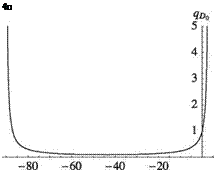
Figure 4.26. Normalized divergence dynamic pressure for an elastically uncoupled, swept wing with GJ/EI = 1.0 and e/l = 0.02
Thus, for a wing structural design with given values of e, GJ, EI, and l, there are values of sweep angle Л for which the divergence dynamic pressure goes to infinity or becomes negative, implying that divergence is not possible at those values of Л. Some values of Л make the numerator infinite because tan^) blows up, whereas other values make the denominator vanish or switch signs. Therefore, within the principal range of -90° < Л < 90°, we can surmise that divergence can take place only for cases in which |Л| = 90° and 3n2r = 76. Sign changes have the following consequences: Divergence is possible only if -90° < Л < Лто, where
Thus, Eq. (4.110) can be written as
![]()
![]() 0p_
0p_
qP0
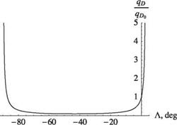
In other words, we avoid divergence by choosing Л > Лто, and the divergence dynamic pressure drops drastically as Л is decreased below Лто. Because Лто is likely to be small, this frequently means that backswept wings are free of divergence and that divergence dynamic pressure drops drastically for forward-swept wings. Because Лто is the asymptotic value of Л from the approximate solution, which is greater than the limit-point value of Л from the exact solution, we may surmise that the approximate solution provides a conservative design. Figure 4.26 shows the behavior of divergence dynamic pressure for a wing with GJ /EI = 1.0 and e/l = 0.02. The plot, as expected, passes through unity when the sweep angle is zero. Because Лто is very small for this case, the divergence dynamic pressure goes to infinity for a very small positive value of sweep angle. Thus, even a small angle of backward sweep can make divergence impossible. Figure 4.27 shows the result of decreasing GJ/EI to 0.2 and holding e/l constant. Because Лто increases, the wing must be swept back farther than in the previous case to avoid divergence.
Figure 4.27. Normalized divergence dynamic pressure for an elastically uncoupled, swept wing with GJ/EI = 0.2 and e/l = 0.02
 Because e can be positive, negative, or zero, qD0 also may be positive, negative, or zero. Thus, by normalizing qD by qD0, we may obfuscate the role of the sign of e on qD. In such cases and perhaps others, it is more convenient to write Eq. (4.112) in a form that does not depend on qD0. One way to accomplish this is to eliminate qD0 from the expression for qD using Eqs. (4.109) and (4.111), yielding
goad _ 19 [1 + tan2 (Л)] (4 _
EI 3 [tan^cx,) – tan^)] .
making it clearer that divergence occurs only when -90° < Л < Лх, regardless of the sign of e. This form of the formula also shows more explicitly that EI has a role in the design of swept wings that are free of divergence.


