TRANSFER FUNCTIONS
It is convenient to introduce a terminology for the statement of physical problems in the s language. Suppose that an input Yt{t) to a mechanical or electronic system is connected with the output Y0(t) by a linear differential operator:*
№ Y0(t) = 7,(0 (1)
In general, the transformed equation can be written as
y0(s) = F(s) Vi(s) + A(s) (2)
where
y0(s) = js?{ вдк), у is) = ад*}
* An integral operator of the convolution type leads to the same result.
F(s) is a function of s depending solely on the operator /(£>), and A(s) is a linear function of the initial values of Y0(t) and its derivatives.
If F(s) tends to a finite value when s -> + 0, the limit
lim F(s) — К (3)
s—>+0
is defined as the gain, and the function
GW = ^(S) (4)
is called the transfer function of the given operator.
 |
|
To clarify the physical meaning of the gain and the transfer function, let us consider the following simple example:
 |
|
It follows that
|
Y0(t) = (1 – e-«*) 1(0 |
In the special case Yt(t) — l(r), so that yfs) = l/s,
The input and output are shown in Fig. 10.9. It is seen that the output lags behind the input, and that, at a time t — T, the output has reached 63 per cent of its asymptotic value for t -> со. The limiting ratio
shows that the gain К represents the limiting value of the response to a unit step function as t -» со.[27]
In the special case F,(0 = A ewt where A is a constant,
Hence,
вд-ГГЙ5′<~’"”Че“) (10)
The first term tends to zero as t increases; it represents the transient
l
![]()
![]() Yt(t)
Yt(t)
 |
0
disturbance associated with the initial application of Yt(t). The second term represents a steady-state solution. The ratio
[ ^o(Q]steady ____ ^ П11
Yt(t) ~ 1 + icoT ( ’
is the same as F(iw) obtained from F(s) by replacing s with ico. Thus, for a sinusoidal input,
[ Fo(0]steady “ F(io)) YJt) (12)
It is clear then that F(m) represents the frequency response of the dynamic system, and that the gain К represents the limiting value of the response when со -» 0. The transfer function G{ia>) is the ratio of the frequency response to the response at zero frequency.
It is convenient to write the complex vector G(ico) in terms of its magnitude M and its phase angle в,
G(ico) = Me* (13)
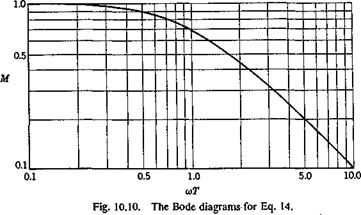
For the present example, Eq. 7 gives
M = ;■ tan в — — CoT (14)
Vl + со2Г2
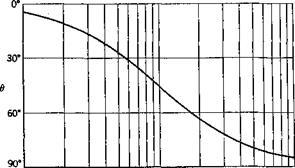
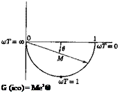
It is customary in electrical engineering to plot M and в as functions of со on a logarithmic paper (the Bode diagrams), and also to plot the locus
|
0.1 0.5 1.0 5.0 10.0 uT |
|
|
 |
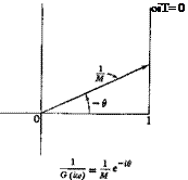 |
of G(im) as a vector on a complex plane, or the locus of jG{m) — (1 jM)e~id (the Nyquist diagrams). For the example defined by Eqs. 5, the Bode and Nyquist diagrams are shown in Figs. 10.10 and 10.11.
Fig. 10.11. The Nyquist diagrams for Eq. 14.
Evidently F(ico) is exactly the mechanical admittance defined in § 8.1. Let us consider the combination of several mechanical systems into a circuit. For a series arrangement of n elements as shown in Fig. 10.12, let the rth element have a gain Kr and a transfer function Gr(ia>) — МгегЄ’.
![]() , У п~Уо
, У п~Уо
Fig. 10.12. Combined elements.
This series array is equivalent to a single block having a transfer function G(im) and gain K:
К = KXK2 ■ ■ ■ Kn
G(im) –= ■ ■ • (Mnei6-) (15)
= (AfjAfa • • • Мп)еі(в’+в*+”’ +e")
The over-all transfer function G(ia>) = Меів can thus be determined:
![]() logjo M = log10 Mt + log10 M2 + • ■ • + log10 Mn
logjo M = log10 Mt + log10 M2 + • ■ • + log10 Mn
0 — 0i + 02 + ‘ ‘ ‘ + 0«
As another example a simple feedback servo is shown in Fig. 10.13. The input у{ passes through a block with gain Kx and transfer function Gx{s)
|
(Д ~ У*‘(Д ~ агУ’ •••(■?- атУп (Д – b^Hs – b2)x‘ •••(*- bnf- |
|
|
|
|
|
|
|
|
|
|
|
|
|
|
 |
|
|
|
|
are the poles; the positive integers уъ, м2, • • * j A2> • are the
orders of the zeros and poles, respectively. We assume < SA,-.
The location of the poles is important in determining the stability of the solution T0(!) which can be derived according to Heaviside’s expansion theorem. Expanding G(s)/s into partial fractions, we have terms of the form
![]() (2)
(2)
associated with each pole Ьг. Therefore, when the input Y{(t) is a unit-step function, yt(s) = 1 js, the inverse transform involves the term
Obviously the solution (3) is “stable” (remains finite as t -> oo) if the real part of b{ is negative, and is “unstable” (becomes unbounded) if the real part of b{ is positive. Thus a necessary condition for stability is that the transfer function should have no poles in the right half-plane R1 л – > 0. This conclusion holds also for transcendental transfer functions: If y0(s) has no singularity on the right half-plane R1 s > 0, then the inverse Y0(t) remains finite as t -» oo. If y0(s) has a pole on the right half-plane, then Y0(t) becomes infinitely large as t -> oo. (See footnote on p. 360.)
Hence, if the transfer function G(s) is a rational function, the problem of stability is to find whether the real parts of all the roots of the denominator are negative.
The conditions for a polynomial with real coefficients
![]() P(s) = p0sn + p1sn-1 + • • • 4- pn-lS + Pn
P(s) = p0sn + p1sn-1 + • • • 4- pn-lS + Pn
to have only pseudo-negative roots (i. e., the real parts of all the roots are negative) are the well-known Routh-Hurwitz conditions. They are given in Appendix 2. This algebraic problem has been generalized to include polynomials with complex coefficients by Sherman, DiPaola, and Frissell.11,20,11-21 An application of these results solves the stability problem completely when G(s) is a rational function.
A different method is introduced by Bode and Nyquist (see Ref. 10.10) and is based on Cauchy’s theorem in the theory of functions of a complex variable. It is applicable to transcendental transfer functions.
Let S be a region on the (x, y) plane bounded by a simple closed curve C. A complex-valued function f(x, у) = ф(х, у) + іxp(x, у) defined in S may be regarded as a function of a complex variable z — x + iy and written as f(z). When 2 traces the curve C, the locus of the complex
 |
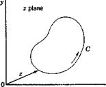 |
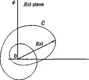
number f(z), when plotted on a complex plane, gives a curve C (Fig. 10.15). Now there is a theorem in the theory of functions of a complex variable which states that iff(z) is analytic in S and continuous on C, and does not vanish on C, then the excess of the number of zeros over the number of poles of f{z) within C is (1/277) times the increase in argjz) as z goes once around C in the positive direction.[28] This result is sometimes called the principle of the argument, and is easily derived from the theorem of residue, considering the residue of the function f'(z)/f(z) in C. A zero of order r is counted as r simple zeros, and a pole of order s is counted as j simple poles. The positive direction of C is so defined that, if an observer
Fig. 10.15. Locus of/(z) as z traces a closed curve C.
moves along the curve C in the positive direction, the region S enclosed by C appears to his left-hand side.
This principle can be applied as follows. If we wish to find the number of zeros of f{z) in a contour C, we determine (a) the change in the argument of f(z) as г goes around C in the positive direction, and (b) the number of poles off(z) in C. Then
о. ^ change of argument of f(z) . , . „
No. of zeros in C — —:———————————— + no. of poles in C
277
The number of poles can usually be determined by inspection. In particular, iff(z) is a polynomial, it has no pole in any contour C.
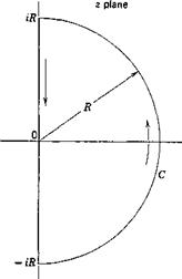
As a particular application, if the number of zeros of jz) in the right half-plane, R1 z > 0, is to be found, we may consider a contour C con
sisting of a large semicircle of radius R in the right half-plane (Fig. 10.16). In the limits when R tends to infinity, the entire right half-plane will be enclosed in C. Observe the locus off(z) as г goes round C once. If it encircles the origin of the f{z) plane n times in the counterclockwise direction, f{z) changes its argument by Ъпт. If the number of poles in the right half-plane is known to be p, then the number of zeros in the right half-plane is n + p.
 |
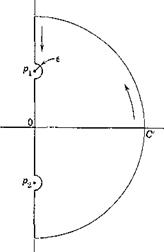 |
The contour C must not pass through any pole or zero of /(г). If there are zeros and poles on the desired contour C, the difficulty can be
Fig. 10.16. A semicircular Fig. 10.17. A deformed semicircular contour. contour.
avoided by making a deformation of the contour in the neighborhood of these points. Thus, as shown in Fig. 10.17, if pt, p2 are poles on the imaginary axis and C is chosen as semicircle, we may take a deformed contour C which circumvents the poles by small semicircular arcs of radius e and let e 0. If px is a pole of order n, we may write, in the neighborhood of px,
where g(z) is finite in the neighborhood of px. Let z — px = sea, ‘then
№ = £ Ырд + 0(e)] Є~іп0
Thus, when z goes around the small arc from в = тт/2 to в = — w/2, the change in phase off(z) is rm.
When the contour C is symmetrical with respect to the real axis, it is useful to remember that, when f{z) is a polynomial or a rational function with real coefficients, or is a combination of elementary functions with real coefficients,
/©=/(г)
where z and / denote the complex conjugate of z and /; i. e., z — x + iy, z = x — iy, etc. Thus, if f(z) corresponding to the upper half of the contour C is known, that corresponding to the lower half can be obtained by a mirror reflection in the real axis.


