Wake Boundaries
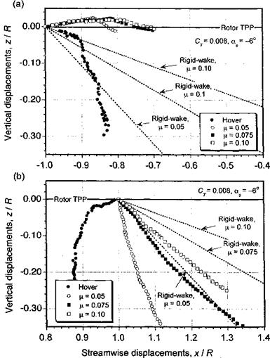
An understanding of the position of the rotor wake boundaries in forward flight can give much useful information to the rotor analyst. Leishman & Bagai (1991) and Bagai & Leishman (1992b) have examined the positions of the tip vortices generated by an isolated rotor and also a rotor with an airframe. The flow visualization results were obtained using shadowgraphy. The measured wake boundaries are plotted in Fig. 10.10 for hover and in forward flight at three advance ratios. Also shown are the positions of the wake that can be predicted on the basis of momentum theoiy considerations alone (i. e., a rigid-wake; see later in Section 10.7.5). Clearly, the correlation with the measured displacements is poor, and the results confirm what can already be deduced from Fig. 10.8, namely that there are considerable mutually induced effects between vortex filaments inside the rotor wake at lower advance ratios. This leads to a powerful longitudinal (and also a lateral) asymmetry
|
Figure 10.1G Tip vortex displacements in an x-z plane at the longitudinal centerline of an isolated rotor. Four-bladed rotor, CT = 0.008, forward shaft tilt angle of 3° in forward flight, (a) Front of rotor disk, (b) Rear of rotor disk. Data source: Leishman & Bagai (1991). |
of the wake that cannot be predicted on the basis of momentum theory alone. Notice from Fig. 10.10(a) that the vortices at the leading edge of the disk are initially convected above the blades and the rotor TPP within the first 90° of wake age, compared to the rear of the disk [see Fig. 10.10(b)], where the wake vortices are convected quickly away from the rotor. This is because of a small region of upwash velocity at the leading edge of the disk and a strong longitudinal inflow gradient, which has its source in the skewness of the wake (see also the discussion in Section 3.5.2).


