Our heavyweight helicopter equal in the world does not have
In Rostov started production of the most load-lifting rotary-wing car The Russian holding «Helicopt[...]

Everything about aircrafts and helicopters. News and events in aviation worldwide. Civil, transportation, military helicopters and airplanes.

Everything about aircrafts and helicopters. News and events in aviation worldwide. Civil, transportation, military helicopters and airplanes.

Everything about aircrafts and helicopters. News and events in aviation worldwide. Civil, transportation, military helicopters and airplanes.

Everything about aircrafts and helicopters. News and events in aviation worldwide. Civil, transportation, military helicopters and airplanes.


The probes used to measure flow speed, as we have seen, must be aligned with the direction of velocity and must have low sensitivity to the angle of attack. If the direction of the flow has to be known, it is mandatory to use probes with high sensitivity to the angle of attack (direction probes). Typically the shapes of these probes are simple bodies (sphere, cone, wedge, tube etc.). In all configurations, one or two pairs of taps, arranged symmetrically to the axis of the probe, are inclined on the direction of stream. With a pair of taps, measures of direction in 2D fields are obtained, in 3D fields, at least two pairs of taps are used.
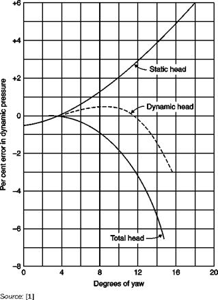
For each body the aerodynamic sensitivity to the angle of attack is represented by the tangent to the curve Cp(a): the sensitivity of a Pitot tube (Figure 2.4) is negligible up to 10° and its maximum between 40°
|
Performance of standard Pitot-static tube in yaw
|
and 60°. The sensitivities of cylinders and spheres show a similar behavior (Figure 2.2). Usually the pressure taps are positioned where the sensitivity is greatest, the only exception is the position where Cp = 0 used when, with the probe axis aligned with the speed, also the pressure pm must be measured. However, if precise measurements of pm are required, it is preferable to use a separate static tube.
Two different strategies able to measure the direction of velocity can be used:
1. The direction probe is rotated into the stream until the pressure difference between two opposite taps is zero (null reading method). The axis of the probe is then in the same direction of the stream in the limits of the accuracy of the instrument; construction errors can be
![]()
eliminated by repeating the test with the probe rotated at 180° and making an average between the two readings.
2. The probe is fixed in a reference direction (fixed method): the pressure difference between opposite taps is read and the corresponding angle between the axis of the probe and the direction of stream velocity is obtained from a calibration curve.
The first method is more immediate because it does not require calibration but has the disadvantage that the probe must be oriented with precision, which is particularly difficult if the probe is to be moved in a closed test chamber, or two angles in two orthogonal planes are to be measured (3D probes).
Calibration is often performed in a free jet flowing from a nozzle placed at the exit of a large stagnation chamber; the pressure difference between each pair of orifices divided by dynamic pressure is reported for each angle of the probe with the known velocity direction:
p-p = f(a)
Many types of probes are used, the choice is influenced by the Mach number of the stream, the type of flow (2D or 3D) and by considerations of robustness and ease of calibration. At low Mach numbers, the sensitivities of all the usual types of direction probes are of the same order, with values of d[(p2 – p1)/q]/da = 0.04 – r – 0.08 per degree. Using a suitable gage the direction of stream can therefore be determined with an approximation of 0.1°. The sensitivity decreases with increasing Mach number.
Measures of direction of velocity are rarely made in a uniform stream: there are almost always gradients of speed and therefore the errors due to gradients of stagnation pressure are present. If, on the other hand, the shear rate is strong, the measure of a direction probe is meaningless: even when the probe is aligned with the stream, there is a difference in pressure between the two taps because they see different speeds. These effects can be mitigated by minimizing the distance between the taps and using taps with small diameters.