Models for Wake Rollup, Jets, and Flow Separations
The thin wake behind lifting wings tends to follow the local velocity (Eq. (9.18)) which results in a wake rollup due to the lifting surface and the wake-induced velocity. This condition causes the shape of the wake to be unknown when the boundary conditions for the potential flow are established. Traditionally, the shape of the wake is assumed to be known (e. g., planar vortex sheet) and after the solution is obtained the validity of the initial wake shape can be rechecked. In Chapter 14 two methods used by two panel codes will be presented to calculate the wake shape (VSAERO-wake relaxation,92 and PMARC-time stepping9 6’9’7).
Since the wake is modeled by a doublet/vortex distribution, it is possible to extend this method for modeling jets and even shear layers of separated flows. Details about models to represent the effect of jets can be found in Refs 9.2 and 9.6, while models to treat some effects of flow separation will be presented in Chapter 14.
REFERENCES
9.1. Lamb, H., Hydrodynamics, Dover Publications, 1945.
9.2. Maskew, B., “Program VSAERO Theory Document,” NASA CR 4023, Sept. 1987.
9.3. Johnson, F. T., “A General Panel Method for the Analysis and Design of Arbitrary Configurations in Incompressible Flows,” NASA CR 3079, May, 1980.
9.4. Gerald, F. C., Applied Numerical Analysis, 2d edn., Addison-Wesley, Reading, Mass., 1980.
9.5. Bristow, D. R., and Hawk, J. D., “Subsonic Panel Method for Designing Wing Surfaces from Pressure Distributions,” NASA CR-3713, July 1983.
9.6. Ashby, D., Dudley, M., and Iguchi, S., “Development and Validation of an Advanced Low-Order Panel Method,” NASA TM 101024, 1988.
9.7. Ashby, D., Dudley, M., Iguchi, S., Browne, L., and Katz, J., “Potential Flow Theory and Operation Guide for the Panel Code PMARC,” NASA TM 102851, March 1990.
PROBLEMS
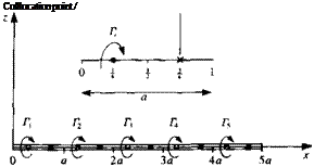
9.1. Solve the problem of a flat plate at an angle of attack of a using the lumped-vortex element. Divide the chord to five equal panels of length a, as shown in Fig. 9.19.
(a) Calculate the influence coefficient matrix a, t. Is this is a diagonally dominant matrix?
(b)
 |
 |
Calculate the lift and moment coefficients. How do these compare with the analytical results of Chapter 5.
FIGURE 9.19
Discrete vortex model for the flat plate at angle of attack.
9.2. Calculate the lift and moment coefficient (about the origin, x = 0) of the two flat plates shown in Fig. 9.20. Use a single-element lumped-vortex model to represent each plate and investigate the effect of the distance between the two plates on their lift (repeat your calculation with gap values of c/2, c, 2c, 4c).
Z(l
 |
Г r2


