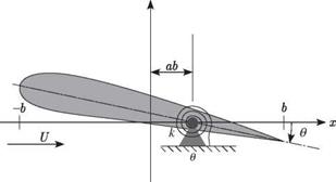
One-Degree-of-Freedom Flutter
To illustrate the application of classical flutter analysis, a simple configuration is treated first. This example is a one-degree-of-freedom aeroelastic system consisting of a rigid two-dimensional wing that is permitted to rotate in pitch about a specified
|
|||
|
|||
 |
|||
|
|
||
|
|||
 |
|||
|
|||
|
|||
|
|||
|
|||
|
|
||
|
|||
|
|||
To solve this equation, it is presumed that the configuration parameters Ip, , and b
are known. The unknown parameters that describe the motion and flight condition are rn, pTO, k, and Mro. These four unknowns must be determined from the single algebraic equation, Eq. (5.47). Because the aerodynamic coefficient, mp(k, Mro), is complex, it can be written as
me (k, Mro) = Щ[тв (k, M«>)] + i»[m0 (k, Mro)] (5.48)
As a consequence, both the real and imaginary parts of the algebraic relationship must be zero, thus providing two real equations to determine the four unknowns. Therefore, two of the unknown parameters should be specified. A fixed altitude is chosen that specifies the freestream atmospheric density, pro. The second parameter to be fixed is the Mach number, which can be given a temporary value of zero. This, of course, implies that the flow is incompressible and the aerodynamic-moment coefficient is then only a function of the reduced frequency. The governing algebraic equation now can be written as
Equating the imaginary part of the left-hand side to zero gives a relationship that can be solved for the reduced frequency, kF, at the flutter boundary; that is
![]() S[mp (kF, 0)] = 0
S[mp (kF, 0)] = 0
With kF known, Щ[те (kF, 0)] can be numerically evaluated. Equating the real part of the left-hand side to zero now enables the frequency, mF, to be determined from
/ Щ_у = 1 + nproЬ*Щ[тв (kp, 0)] (5 51)
&F / Ip
Now that kF and mF have been determined, it is possible to compute the flutter speed as
The flutter speed determined by the previous procedure corresponds to the originally specified altitude and is based on an incompressible representation of the airloads. After this speed has been determined, the speed of sound, cro, at the specified altitude can be used to find the flutter Mach number as
Uf
Mp = — (5.53)
cro
If this flutter Mach number is sufficiently small to justify the use of incompressible aerodynamic coefficients, then the altitude-speed combination obtained is a point on the flutter boundary. If the flutter Mach number is too high to validate the incompressible approximation, then the entire procedure should be repeated using aerodynamic coefficients that are based on the initially computed flutter Mach number. Using the standard atmospheric model, which relates density and the speed of sound, this iterative scheme converges to a flight condition on the flutter boundary.


