Properties of vortex flows over slender wings
6.3 We have already discussed briefly the flow over lifting slender wings in section 3.3 (Fig. 3.6) and vortex sheets as the main flow element involved in section 2.4. Now we must describe the flow in more detail – a good understanding of the flow properties is indispensable for the aerodynamic design of slender aircraft. Our knowledge of this type of flow stems partly from theoretical investigations, to
be discussed below in section 6.4, and partly from experimental observations, to be discussed below in section 6.5, where notable contributions have been made by S В Berndt & К Orlik-RUckemann (1948), T Ornberg (1954), G H Lee (1955), P T Fink (1957), D J Marsden et at. (1958), A P Cox (1959),
A Stanbrook & L C Squire (1959), N C Lambourne & D W Bryer (1958) and (1960), P В Earnshaw (1961) and (1964), D Hummel (1965), D G Mabey (1968), D Hummel & G Redeker (1972), and others. We refer also to flow visualisation studies by R L Maltby (1956, unpublished) and (1962), by J-C Morey & Q Zuber (1974) and those summarised by H Werld (1973) and to select bibliographies of early work on slender wings compiled by E L Houghton (1963) and by J P Street &
M D Miller (1970). Here, we follow mainly the concepts developed by E C Maskell (1962) and J H В Smith (1975).
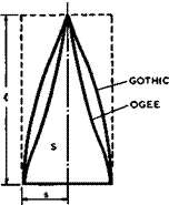 |
The geometry of the wings to be considered is not restricted to delta plan – forms with straight edges. Curved beading edges with streamwise tigs are preferable to straight edges on many grounds. This leads to two classes of planform shape, one where the leading edge remains convex along its length, and another where the leading edge has an inflection point (see Fig. 6.9).
r
Fig. 6.9 Planform shapes of slender wings
Typical of the first class of so-called gothio wings is the planform given by
Typical of the second class of so-called ogee wings is the planform given by
The planform shape parameter p of gothic wings is necessarily greater than the value p = 1/2 for the delta wing if the trailing edge is unswept, p is 2/3 for the particular shape given by equation (6.9). Its centre of area is situated at x/fc = 0.625 . Ogee wings can have values of p smaller than 1/2 and thus offer some advantage because the drag can be lower, according to
(4.140). p is 0.475 for the particular shape given by С6.Ю). Its centre of area is situated at x/f. = 0.687 . All the slender wings to be considered have a pointed apex and approach geometrically conical shapes in that neighbourhood. The flow may then also be approximately conical in a region downstream of the apex. Thus conical flows have the same fundamental significance for slender wings as the classical twodimensional aerofoil flow has for classical and swept wings. These basic matters have been set out in detail by J H В Smith (1972). An understanding of the structure of these conical flows is needed for our purpose.
A flowfield is conical if there is a point, called the vertex of the flow, such that the velocity does not vary along rays drawn from the vertex. The structure of both conical and twodimensional flows is most clearly revealed by the properties of certain streamsurfaces. In twodimensional flow, these are the streamsurfaces which are orthogonal to the plane of the flow and cut it in the familiar streamline pattern. In conical flow, the streamsurfaces of corresponding significance are those which are conical and, consequently, pass through the vertex of the conical flow. Their properties are revealed by the curves in which they intersect a sphere centered on the vertex, but it is more convenient to draw plane maps of these curves, obtained by projection.
For the present purpose, it is sufficient to project from the vertex on to a plane on the downstream side of the vertex. The whole region of disturbed flow can then be represented on such a plane for the slender—body flow past conical wings, and so can the region of interest in a conical vortex-sheet core. The curves on the sphere and their planar projections will be referred to as conical streamlines. There is a physical difference between these and twodimensional streamlines. In steady twodimensional flows, streamlines are the paths of fluid particles and the condition of continuity prevents them from running together. Conical streamlines, on the other hand, are only projections of space curves which form the actual streamlines and particle paths of the threedimensional flow. Continuity does nothing to prevent conical streamlines from running together. It is the occurrence of certain singular points, such as nodes and spiral points, at which conical streamlines run together, that most readily distinguishes patterns of conical streamlines from patterns of twodimensional streamlines. For a detailed discussion of these singular points we refer to J H В Smith (1972).
Before we consider conical streamline patterns over slender wings in more detail, we look briefly at some mainly experimental evidence, so that we are quite aware from the outset of the advantages and appropriateness of the conical-flow approximation and also of its limitations, in the same way as we have previously pointed out the powers and the limitations of the twodimensional aerofoil flow in the context of swept wings. This will at the same time expose some problems which will have to be explained and clarified.
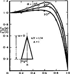
In Fig. 6.10, we have plotted the local normal force coefficient CN(x) , integrated from pressure differences along the span for various chordwise stations, from measurements at low speeds on a delta wing by D H Peckham
(1958) . In a conical flow, %(х) should be constant and equal to the extrapolated value Cjj(0) at the apex. We find that this is approximately true in the region downstream of the apex for large values of the angle of incidence but less so for smaller angles. This indicates that the wing thickness brings about some departure from conicality, which matters more when the angle of incidence is small. This effect will be explained in section 6.4 below. We find also that the trailing edge has a large upstream influence: the Kutta condition demands zero load at the trailing edge and thus conical flow cannot
LIVE GRAPH
Click here to view
|
x/« Fig. 6.10 Chordwise distribution of integrated spanloading over delta wing at low speeds. After Peckham (1958) |
exist in its neighbourhood at subsonic speeds. Again, this effect will be explained below in section 6.5 but, in this case, no theory to determine this very large and important effect adequately is as yet available.
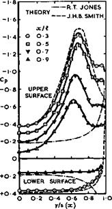
Fig. 6.11 shows pressure distributions over the surfaces of a thin delta wing in more detail, from extensive measurements by D Hummel & G Redeker (1972). Theoretical results for attached conical flow (R T Jones (1946)) and for fully-separated conical flow (J H В Smith (1966)) are also given. We find that the solution for attached flow is quite inadequate, but that the solution for separated flow gives quite a good representation in the region near the apex, except in the immediate neighbourhood of the leading edge where some effect occurs which will have to be explained below. Again, the influence of the trailing edge is clearly apparent: it does not seem to affect the character of the flow but mainly the actual values of the pressure.
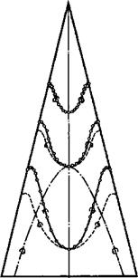
Fig. 6.12 shows the distribution of the bound vortices over the surface of a delta wing at low speeds, from measurements by D Hummel & G Redeker (1972), where the vorticity vector was determined from the magnitude and direction of the velocities just outside the boundary layers over the upper and lower surfaces of the wing. These results indicate again that the theory for conical separated flow gives a good approximation in the neighbourhood of the apex. Departures from conical flow near the trailing edge are also clearly shown. Both theory and experiment lead us to expect the shedding of some vortioity of the rwrong* sign from the trailing edge (i. e. opposite to the sign of the main vorticity shed from the leading edge), as already indicated in Fig. 3.6. The consequences of this feature will be discussed in section 6.5 and attempts to eliminate it in section 6.4.
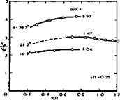
Another example in Fig. 6.13 shows the axial velocity component along the centre of one of the rolled-up vortex cores above a slender delta wing, from
|
|
|
|
|
|
Fig. 6.12 Distribution of bound vortices over a slender wing at low speeds
LIVE GRAPH
 Click here to view
"Fig. 6.13 Axial velocity at the centre of vortex cores over a delta wing at low speeds. After P В Earnshaw (1961) measurements by P В Earnshaw (1961). Although the shape of the core itself was observed to be nearly straight along a ray from the apex of the wing over much of its length, the axial velocity is seen to vary, both in the region near the apex and in the region influenced by the trailing edge. We shall
explain below the reasons for these effects and what their consequences are. One is caused by viscosity and the other by variations of the pressure field in the neighbourhood of the trailing edge. We note that the axial Velocity is several times that of the mainstream, a remarkable feature in a flow where otherwise the wing causes only small perturbations.
The last example is concerned with the development of the threedimensional boundary layer in conical inviscid flows. Quite generally in viscous flows, the conical nature cannot be preserved and the flow variables must to some extent vary along rays through the vertex. For instance, a boundary layer evidently grows along such a ray in a non-conical manner. We must, therefore, expect that complications arise and that the full threedimensional flow must be considered whenever the boundary-layer displacement thickness becomes comparable with some characteristic dimension of the wing (see e. g. J C Cooke & M G Hall (1962)). However, the conicality of the external inviscid flow may still lead to some simplification in the boundary-layer behaviour. For laminar boundary layers, F К Moore (1951) and W D Hayes (1951) have shown that there is then a parabolic similarity along rays. If u and v are velocity components in the boundary layer along and perpendicular to the rays, then
u = f(X,0) , v = g(X,0) , with X = z//r, (6.11)
where z is the distance normal to the surface, r is the distance from the vertex, and 0 is constant along a ray. One consequence of this behaviour is that the limiting streamlines in the surface (or skin friction lines) make a fixed angle with the ray, independent of r. This feature has often been observed.
With these reservations in mind, we can now describe some properties of conical flows in more detail, following the presentation by J H В Smith (1972), where a rigorous mathematical formulation may be found. Here, we want to look at some typical conical streamline patterns; relations for those properties which we need to know will follow later.
Consider first the incompressible flow past a flat thin delta wing (with its trailing edge at infinity downstream) at an angle of incidence a without flow separation from the leading edges. The wing is assumed to be slender so that, if к ■ s/Я. is the tangent of half the angle at the apex, then к ^ 1 . In a conical flow, the three independent space coordinates x, y, z are reduced to the two combinations n = y/x and Z, = z/x. This implies that flows are the same if the similarity parameter
— – a
к s/St,
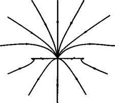
has the same value for each. If a/к < 1 , the conical streamlines are as shown in Fig. 6.14. Note the fundamental difference between this pattern and the streamline pattern of the twodimensional flow at right angles to a flat plate in Fig. 3.2. Now, singular points occur on the wing. Two saddle points move in along the lower surface from the leading edge, when a/к = 0 , to the centre line, when a/к = 1 . On the centre line on the top and bottom surfaces, there is a node if a/к < 1 and a saddle point if а/к > 1 . The node on the upper surface of the wing moves up into the stream at the same value of а/к as the node on the lower surface disappears. At a/< = 1 , higher-order singularities appear, and a sketch of the behaviour of the conical streamlines
 |
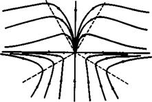 |
near the singular points in this case is shown in Fig. 6.15. The essentially unrealistic feature of all these flows is that the flow is supposed to be turned around the leading edges through 180° at an infinite velocity. There is at most one singular point on the wing surface at which fluid leaves the wing, i. e. one separation line. This appears in the plane of symmetry so that no vorticity is shed from it. In a realistic flow pattern, flow separation occurs at the edges, associated with the shedding of vorticity and the formation of vortex sheets.
Fig. 6.14 Flat delta wing in attached Fig. 6.15 Neighbourhood of centre flow, а/к < 1 line of flat delta wing, а/к = 1 .
After J H В Smith (1972)
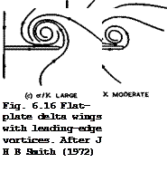
Three flow patterns with leading-edge vortex sheets are sketched in Fig. 6.16, for increasing values of the similarity parameter а/к. At the smallest value, there are two saddle points of attachment and one saddle point of separation on each half of the wing, with two nodes on the centre line and two singular spiral points of leading-edge vortex type. At the intermediate values of а/к, these singular points on the upper surface have united at the centre line, so that two saddle points and a node become a single saddle point. Similarly, at the largest value of а/к, the singular points on the lower surface have united at the centre line.
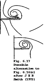
We can imagine that the points of attachment on the lower surface reach the centre line before those on the upper surface; but there is no evidence that this ever happens. The sketches in Fig. 6.16 suggest that, at the higher angles of incidence, all the flow ends up in the vortex cores far downstream. This need not happen, and Fig. 6.17 shows how a node and a saddle point can be introduced in the plane of symmetry to provide an alternative destination for part of the fluid. Again, there is no evidence that this flow pattern occurs in practice.
What does occur in a real flow is a secondary separation of the boundary layer on the upper surface of the wing underneath the vortex cores. As can be seen from Fig. 6.11, the cores induce pronounced suction peaks on the wing so that the outflow towards the leading edges, which is a feature of all the streamline patterns in Figs. 6.16 and 6.17, subsequently meets an adverse pressure gradient that, in turn, causes separation of the boundary layer. This results in the formation of a further singularity of the vortex-sheet type on each
 |
 |
half of the wing. A sketch of the conical streamlines for a moderate value of а/к is shown in Fig. 6.18. The cores of the secondary vortex sheets
Fig. 6.18 Flat-plate delta wing with secondary separation. After J H В Smith
(1972)
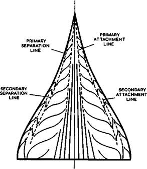
locally increase the suction on the wing surface, and this accounts for the departure of the measured pressures in Fig. 6.11 from those calculated for a flow with primary vortex sheets only. No difficulty arises in constructing streamline patterns with further separations under the secondary vortex sheets etc., and tertiary separations have, in fact, been observed. These flow properties are clearly observable from the pattern of limiting streamlines in the surface of the wing (see section 2.4). Fig. 6.19 gives a typical example for an ogee wing with primary separation from the leading edges, where the
|
Fig. 6.19 Streamline pattern in the upper surface of a slender wing at low speeds, a = 15° |
flow is not conical but nevertheless exhibits the features outlined above. There is a region of nearly parallel flow between the primary attachment lines around the centre line of the wing. The air drawn into the cores of the primary vortex sheets moves sideways until it meets the secondary separation line. A secondary vortex sheet springs from there and causes a secondary attachment line on the wing, which divides the air which is drawn into the secondary vortex cores from that which is not. The position of the secondary separation line is not fixed and thus depends on the state of the boundary layer and on the Reynolds number, as will be discussed further in section 6.5.
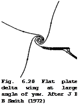
Conical flows may also exist when there is no plane of symmetry. Consider, for example, a thin flat delta wing of low aspect ratio yawed to starboard at an angle greater than half its apex angle, so that its port leading edge becomes a ‘trailing edge’. If the flow separates from this trailing edge but remains attached at the starboard leading edge, a streamline pattern like that in Fig. 6.20 results. This flow has been calculated by I P Jones (1975). The resemblance of the streamline pattern near the wing to the twodimensional streamlines in the flow past a flat plate in Fig. 3.3 is not coincidental, since twodimensional flow is a degenerate case of conical flow, in which the vertex of the conical field is infinitely remote.
Consider now the inviscid, incompressible flow past a coherent vortex sheet with a rotled-^up core in more detail. The sheet must originate at some separation line on a solid body, from which vorticity is continually shed.
As already explained in section 2.4, the vorticity is convected along the
local mean flow direction (in which the local vorticity vector also lies) and we may, therefore, think in terms of elemental vortex lines in the sheet along the local vorticity vector. These elemental vortex lines must, in general, have a spiral shape, if vorticity is convected at all. If the sheet is conical in shape, the vortex lines cannot lie along rays from the apex nor at right angles to these. Bearing in mind that the velocity vectors on either side of the sheet are symmetrically placed on either side of the vorticity vector (see Fig. 2.15), we find that the velocity field has not oniy a swirl component vq but also a radial component vr and an axial component vx, in cylindrical coordinates x, r, 6, with the x-axis directed along the axis of the core. There is usually a radial inflow into the core region, which is then converted into axial flow. This is the reason why the core must grow in space, generally in the streamwise direction, and may assume a conical shape. There is also a strong interaction between axial and swirl velocities, and this is one of the key features of threedimensional vortex cores.
An instructive example is the flow in an isolated self-similar oore of oonioal shape:
![]()
 |
S(x, r,8) = r – xf (8) = 0
 |
Solutions for the velocity components at the sheet have been given by D Ktichemann & J Weber (1965) and by К W Mangier & J Weber (1967) as a series in the neighbourhood of the axis
where c and к are free constants. The first terms on the right-hand sides are the leading terms in the mean values, and the second terms are the leading terms in the jumps across the sheet, where the upper signs refer to the
 |
|
outside of the sheet. The shape of the sheet is obtained by integrating
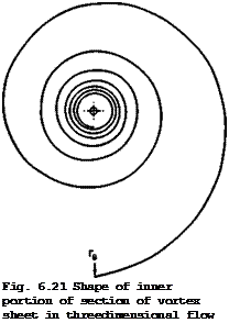 |
The resulting spiral shape, illustrated in Fig. 6.21, is tightly rolled and becomes more nearly circular near the axis. The spiral intersects any circle only once, on entering it.
If there is a varying external velocity field superimposed on the inner core flow, as generated by a nearby wing, then the vortex sheet should have an oval shape, with a factor to its leading term, which varies sinusoidally with the polar angle, as shown by E C Maskell ((1964), unpublished; see also J H В Smith (1966) and N Riley (1974)).
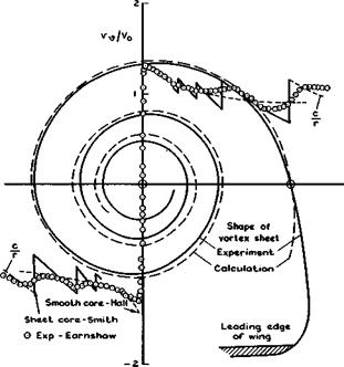
In practice, the relations given above for an isolated conical core represent the shape and the velocity components of vortex cores over slender wings very well. P В Earnshaw (1961) and (1964) carried out tests at low speeds on a thin delta wing with s/f. = J at a relatively high angle of incidence a = 20° , i. e. a/к = 1.4 . The velocity components were measured in two perpendicular traverses through the axis of one vortex core in a plane normal to the mainstream about 2/3 of the wing chord behind the apex where the flow may still be regarded as approximately conical. The trace of what might be called the basic thin vortex sheet was derived from the measured velocity field and is shown as a full line in Fig. 6.22. The inner part of the asymptotic vortex sheet calculated from (6.16) is shown as a dashed line, matching the scale (rg in Fig. 6.21) rather arbitrarily to one point on the outboard side of the measured sheet. Values calculated from equations (6.13) to (6.15) can be fitted to the experimental values of the mean velocity components (the average over the four quadrants) with a single set of the free constants over
|
Fig. 6.22 Trace of vortex sheet over a delta wing and circumferential velocities in a horizontal traverse |
the whole of the traverse region, namely, c = 0.62Vq and к = -0.8 . As can be seen from Figs. 6.22 and 6.23, shape and velocity components are remarkably well represented by the theory for conical vortex sheets in inviscid flow.
The measured circumferential velocity component is shown in Fig. 6.22 by the circles, and the first term in (6.15) by dashed lines, whereas the full lines give the total velocity as calculated from (6.15), including the jumps where the traverse crosses the sheet. This is the typical rolled-up vortex-sheet core we should bear in mind, especially since such vortex flows are so often wrongly represented. This model was first proposed as a conjecture by A Betz (1950) and is now firmly established, theoretically and experimentally.
Analytical solutions can also be obtained when the additional assumption is made that the conical core is also slender, i. e. that vx < Vq (which cannot hold at large angles of incidence, see e. g. Fig. 6.13). It then turns out that the solution is formally the same as that for a twodimensional vortex – sheet core which grows linearly with time. Note that such a correspondence can only obtain in inviscid flows: the Navier-Stokes equations for a steady threedimensional motion can only be transformed into those for an unsteady twodimensional flow by the operator
V J – – J – 0 Эх 3t
2 2 2 2 . . . if the terms Э Vy/Эх and Э v2/3x can also be ignored. This is not
justifiable» in general, especially not near lines of separation. Solutions for slender conical cores have been given by К W Mangier & J H В Smith (1959) and by К W Mangier & С C L Sells (1967). The shape of the cross-section in a plane x = const is
![]()
![]() (6.17)
(6.17)
It differs from that of the non-slender conical core, (6.16), especially near the axis where it is more tightly rolled. For the slender conical sheet,
![]()
![]()


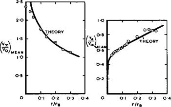 |
(6.18)
and (6.19)
Comparison between (6.14) and (6.18) shows that there is a mean radial inflow into the non-slender core whereas there is none into the slender core. Comparison between (6.15) and (6.19) shows that the mean swirl velocity component increases toward the axis of the non-slender core whereas it is constant across the slender core. Lastly, even though the perturbation to the axial velocity component vx has been ignored in the derivation of. the flow in the slender core, its value is nevertheless implied and the total axial velocity can be determined:
V0 + = cs(> + ks – ln f) ♦ °(!) • (6-20>
9
If the free constants are chosen such that Cg ■ c and 1 + kg = к, the mean values near the axis are the same as those for the non-slender core, (6.13).
In particular, vx increases towards, and becomes infinitely large at, the
axis. This violates the assumption made in its derivation and renders the solution not uniformly valid. Physically, the model of a slender conical core does not make sense. This should he borne in mind when we discuss complete solutions for separated flows in section 6.4.
 |
We turn now to a different model of the flow in the core of a rolled-up vortex sheet growing in space where, according to M G Hall (1961) and (1966), the flow is assumed to be continuous and rotational inside a certain circular boundary r = rg. Physically, this may be interpreted as a situation in which viscous diffusion has smoothed out completely all the discontinuous velocity jumps inherent in the thin-sheet model (see Fig. 6.22) but where viscosity can subsequently be ignored again. We consider an incompressible inviscid steady flow which is governed by the Euler equations, together with the continuity equation. The flow is again assumed to be conical and, in a quasi-cylindrical approximation, variations in the axial direction are taken to be small compared with variations in the radial direction. The equations of motion have been solved by M 6 Hall (1961) and H Ludwieg (1962) for the
К W Mangier & J Weber (1967) have shown that these relations are the first terms in series of powers of r/x, in which the assumption of quasicylindrical flow is not made. Thus these narrow-core solutions hold as long as r/x < 1 .
For these elongated narrow cores, the velocity field induced by them outside their boundaries, i. e. for r > rj, can readily be estimated. For this purpose, the core at any station x is replaced by a circular cylinder of infinite length and radius rB, with a distribution of singularities, i. e. of potential sources, ring vortices and axial vortices, inside the core. Any source distribution q(r) induces only radial velocity components. If q = constant, then vr(r) inside the cylinder is the same as that given by equation (6.22). Outside the cylinder, vr is the same as that induced by a sink line on the axis of strength
Q = 2,rrBvrB. (6.25)
This holds for any distribution of q(r) and of vr(r) inside the core. Any distribution of vortex rings whose strength depends solely on r induces only axial velocity components. These are zero outside the core, whatever vx(r) is
inside. Any distribution of axial vortices whose strength depends solely on r induces only swirl velocity components. The distribution can be adjusted to induce any given velocity distribution ve(r) inside the core. Outside the core, any such vortex distribution induces swirl velocities which are the same as those induced by a line vortex on the axis of the strength
Г = 2lrrBV0B ‘ (6.26)
Thus the velocity field external to any narrow core can be approximated by that of a vortex-sink line along the axis, as is also indicated by the experiments in Fig. 6.22. We note that Q/Г = v,-b/v0b. But even though the external flow is so simple, the flow inside the core is entirely different from solid-body rotation, as is sometimes erroneously assumed. The strong interaction between swirl and axial velocity remains an essential feature also in this smooth-core model, and any model involving a twodimensional rotating flow can never be adequate.
There is a close connection between this smooth model and the thin-sheet model for vortex cores discussed above. This can easily be seen by comparing the solutions (6.13) to (6.15) for the velocity components at the sheet of the core growing conically in space with the solutions (6.21) to (6.23) for those of the corresponding smooth core. The first terms of the former are the same as the latter when the free constants are adjusted as follows:
C = ’ <6-27>
к = і + In rfi. (6.28)
Thus the first terms of the vortex-sheet solution (which are the mean values at the sheet) are actually the same as would occur in a rotational flow.
This remarkable connection between the two core models suggests the concept of a hypothetical mixing process in which viscous diffusion smears out the initial velocity jumps and leads eventually to the mean velocity distribution. This would have to effect a gradual transition from the velocity vector V£ on one side of the sheet to Ve on the other, and only at an infinitely large Reynolds number would the thin vortex sheet with discontinuities in the velocities appear. It would seem rather important that this diffusion process be such that both the velocity component in the mean flow direction along the sheet and that normal to the sheet remain unaltered and that only the lateral velocity component (tangential to the sheet and normal to the mean flow direction) is affected. In that case, the displacement thickness of the hypothetical viscous layer in the mean flow direction would be zero and thus the flow and the pressure field would not be upset. Otherwise, the displacement thickness would widen out the spiral sheet. This conjecture is supported by the solution for a simplified laminar flow along an infinite plane surface, obtained by К W Mangier (1965, unpublished). The sheet is given by z = 0 in a Cartesian system of coordinates and for z = ±°°, u = Uq in the x – direction and v = ±Vq in the у-direction. Boundary-layer type approximations are made and the solution turns out to be
u = V v = ТИ V0 / e * dx’ w = 0 » (6.29)
0
This solution has all the required features. The lateral velocity profile follows the Gaussian error integral; it approaches a linear distribution for small Reynolds numbers; it becomes discontinuous again at infinitely large Reynolds number, i. e. 3v/3z = » for z = 0 and 3v/3z = 0 for z Ф 0 when v ■+■ 0 . Thus the connection between the vortex-sheet core and the smooth core, established above, may not be fortuitous but have some physical meaning. More general vortex motions have been investigated by W Albring (1972).
The relation between convection and diffusion processes in vortex cores has been discussed more thoroughly by E C Maskell (1962). He argues that there must be an inner core in the immediate neighbourhood of the axis where the flow is dominated by viscous diffusion and consequently subject to a marked scale-effect. The solutions given above for inviscid flow cannot hold in this inner core: both the axial velocity component, (6.13) and (6.21), and the circumferential velocity component, (6.15) and (6.23), tend to infinity at the axis r = 0 . The experiments in Fig. 6.23 show that the axial velocity has a finite, albeit high, value on the axis, and the experiments in Fig. 6.22 show a region of effectively solid-body rotation near the axis.
This is exceedingly small – so small, in fact, that most investigators apart from P В Earnshaw (1961) have missed it altogether. These observed properties can be predicted, at least qualitatively, by a theory developed by M G Hall
(1961) and later extended by К Stewartson & M G Hall (1963) and by M G Hall
(1965) . Approximations of essentially boundary-layer type are made to find a solution for the inner viscous flow, which is compatible with the solution given above, (6.21) to (6.24), for the outer inviscid flow. Although the observed trends are well represented by this theory, there are some discrepancies which may be attributed to the fact that the actual inner core is turbulent and not laminar as the theory assumes. Fair agreement can be obtained by replacing the kinematic viscosity in the theory by an eddy viscosity about five times larger. It follows from this physical picture of the vortex core that the boundary of the inner viscous core lies relatively
closer to the axis the higher the Reynolds number. Thus the diameter of the
viscous core does not grow in a conical manner even when the outer inviscid flow may be regarded as conical. Earnshaw has observed a variation of the diameter like x£ with axial distance, x, which is as predicted by Hall’s
theory. Similarly, the axial velocity component vx on the axis r = 0
varies with x, and this explains the departure from conicality over the forward part of the wing, illustrated in Fig. 6.13.
Although rolled-up vortex cores are extraordinarily stable flow elements, there are conditions which restrict their persistence. In the present context of slender wings, such conditions may be set up at low speeds in the region of the trailing edge, where the cores are subjected to a longitudinal adverse pressure gradient which causes a gradual retardation of the axial velocity in the core (Fig. 6.13), and should, according to the theoretical models, leads to some tightening of the spiralling flow. This may go as far as a sudden and abrupt change in the structure of the core, leading to a very pronounced retardation of the flow along the axis, or even to flow reversal, and a corresponding divergence of the streamsurfaces near the axis. There is a range of possible flow patterns, from a highly asymmetric spiral to a bubble with a high degree of axial symmetry. This phenomenon is generally called vortex breakdown. It was first observed by D H Peckham & S A Atkinson (1957)
in the flow field of a slender wing, but it occurs also in other motions, such as swirling flows through nozzles and diffusers, and in tornados, whenever there is a strong interaction between swirling and axial velocity components. Of various further experimental investigations of interest in the present context, we mention those by N C Lambourne & D W Bryer (1961),
J К Harvey (1962), D L I Kirkpatrick (1964), and D Hunmel (1965). What effects vortex breakdown may have on the properties of wings will be discussed in section 6.5. Here, we describe briefly several different explanations that have been advanced, following the reviews by M G Hall (1966) and (1972). Hall points out that each of the explanations has contributed to our understanding and that they are complementary in some respects, but that each has some important shortcomings. So far, none has received general acceptance.
The explanations can he grouped into three categories:
(1) The phenomenon is in some sense like the singular separation of a twodimensional boundary layer (I S Gartshore (1962), M G Hall (1967), and others): the spiralling flow gets so tight that the axial flow is brought to rest at some point on the axis.
(2) The phenomenon is a consequence of hydrodynamic instability (H Ludwieg
(1962) , (1964), (1970)): The swirling flow in an annulus is found to be
unstable with respect to spiral disturbances, which might in suitable circumstances be amplified and induce an asymmetry in the core.
(3) The phenomenon depends in an essential way on the existence of a critical state (H В Squire (1960), T В Benjamin (1962), H H Bossel (1967)): standing waves might exist and disturb the flow, or there might be a transition between two possible steady states of axisyrometric swirling flow, in principle the same as the hydraulic jump in open-channel flow; the transition between two such conjugate flows is from a supercritical flow, which cannot support standing waves, to a subcritical flow, which can.
All explanations have in common that some increase in the swirl parameter at the outer boundary sets off the phenomenon: this may cause an instability; it may lead to a critical state; and it retards the axial flow, especially along the axis. On wings, such conditions and hence vortex breakdown usually occur in the region of the trailing edge, where the flow departs significantly from conicality. Since we have as yet no good theory for calculating either the flowfield of the wing in that region or the structure of the vortex cores, the onset of vortex breakdown and its consequences must be determined by experiment.
Consider now the various effects that compressibility can have. The foremost of these is related to the fact that the flow near the trailing edge cannot be conical and that the departure from conicality at subsonic speeds differs from that at supersonic speeds: the load at the trailing edge vanishes at subsonic speeds (Fig. 6.10) but not at supersonic speeds, and thus the aerodynamic centre moves aft in the transonic speed range (see e. g. S В Gates
(1949) ). At supersonic mainstream Mach numbers, the flow on the wing surface near the trailing edge reaches a local Mach number which is, in general, higher than the mainstream Mach number. On an inclined wing with non-zero trailing-edge angle, the necessary recompression and change in flow direction may be effected through a single oblique shockwave attached to the trailing edge, if the mainstream Mach number is high enough and the trailing-edge angle small enough. However, there may be conditions at transonic speeds where the largest turning angle attainable through a single attached shockwave is smaller than the actual turning angle needed. A system of shockwaves, extending upstream of the trailing edge, may then exist (see e. g. D Ktichemann (1962) and M С P Firmin (1966)). Also, an interaction between the leading – edge vortex sheets and a shockwave from the upper surface of the wing may occur and cause unsteadiness of the forces on the wing and a pitch-up, as observed by E P Sutton (1955).
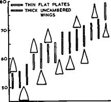
These flow phenomena leave the designer with a trim problem: to bring the centre of lift and the aerodynamic centre, at low speeds as well as at the supersonic cruise, into the right positions relative to the centre of gravity of the aircraft so as to obtain acceptable stability and control characteristics, preferably without control deflection and consequent drag penalty and without actually shifting the eg, e. g. by pumping fuel fore and aft. How this can be achieved and the trim problem solved by the application of camber and twist will be explained below. Here, we note for later reference that the displacement of the aerodynamic centre from its most forward position in the landing-approach condition to its position at cruise is quite substantial but varies little with planform, although the mean positions differ considerably and lie much further to the rear on ogee wings than on gothic wings, as can be seen from the data in Fig. 6.24, collected by A Spence and J H В Smith (1962). But to determine the detailed changes near the trailing edge caused by compressibility on any given wing needs experiments, in the absence of a good theory.
|
°/o LENGTH FROM APEX
Fig. 6.24 Effect of planform on shift of aerodynamic centre between M = 0.3, CT = 0.5 and M = 2.0, C =0.1. After A. Spence & J H В Smith (1962) |
Compressibility also affects other flow elements such as the vortex cores.
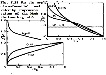
For a wide range of conditions in incompressible flow, a change in the axial velocity increment vx along the outside of the core leads to a more pronounced change in the inner core, due to the presence of swirl. For a compressible, supersonic (inviscid and non-conducting) core, there is no-such amplification: M G Hall (1966) has shown that there is a damping instead and thus the structure of the core is radically different. This has been confirmed by analytical solutions for inviscid conical cores by S N Brown (1965) and by S N Brown & К W Mangier (1967), and some typical results are shown in
 |
|
Fig. 6.25 Effect of compressibility on circumferential and axial velocity components in smooth conical vortex cores. After S N Brown (1964)
the swirl velocity ratio (ve/vx)B – 1 at the boundary. Both these quantities may be arbitrarily specified in Brown*s theory. We see from Fig. 6.25 that compressibility reduce the axial velocity on the axis to a finite value, even though there are infinite gradients there. In addition, the circumferential velocity component Vq is no longer infinite on the axis; instead of increasing towards the axis, it falls to zero. Compressibility thus produces a marked reduction in the variations of velocity and pressure across the vortex core. These effects are accompanied by a tendency towards exceedingly low densities in the core, approaching vacuum near the axis. Measurements by L Gaudet & К G Winter (1961) in the leading-edge vortex core over a slender delta wing in supersonic flow showed a region of such low pressure and density that it was not possible to define the structure of the core. W Merzkirch
(1964) has found similar effects in a corresponding time-dependent vortex core.
The overall flow pattern over a slender wing with leading-edge separation is also affected significantly by compressibility. As in the flow over swept wings (see section 4.2), subsonic, mixed transonic, and supersonic flows may be distinguished. This can be done rigorously for conical flows (see e. g.
D Rtichemann (1962)), and we recapitulate briefly here how the elliptic and hyperbolic regions in the flow, separated by a parabolic surface, can be distinguished from one another. These correspond to the subsonic and supersonic regions of a plane compressible flow. We consider the flow of an inviscid
compressible fluid which is irrotational and isentropic, at least in certain regions, so that the velocity is the gradient of a potential ф. In rectangular Cartesian coordinates, ф satisfies the second-order partial differential equation
( 2 2л /2 2. / 2 2
![]()
(a – v 1ф + la – v 1Ф + a – v |ф x/Yxx У/ УУ zfz
where V = (v, v,v ) = Уф ;
— x у z Y
a is the speed of sound given by
with ap as the speed of sound under stagnation conditions and thus a constant; у is the adiabatic index. This equation may be called quasi-linear because the highest derivatives appear only in linear form. If, in addition, the flow is conical, the velocity potential can be written as
Ф(х, у,2> = xf(n, c) (6.33)
where л = y/x; C = z/x. Then
and (6.31) becomes
[a2(l + n2) – (vy – nvx)2]fnn + 2 jjnCa2 – (vy – nvx) (vz – C^)]^ +
+ [a2(l + C2) – (vz – Cvx)2]fcc = 0 . (6.34)
This is a second-order quasi-linear equation in two independent variables only. At a point (n, C) where the velocity components are (vx, v„,vz) and the local speed of sound is a, the characteristics g(n, C) = 0 or (6.34) satisfy
[a2(l + П2) – (vy – nvx)2](gn)2 + 2{лса2 – (vy – nvx) (vz – C^jJg^g^ +
+ [a2(l + c2) – (vz – Cvx)2](gc)2 = 0 . (6.35)
Equation (6.34) is hyperbolic, parabolic, or elliptic according as the characteristic directions determined by equation (6.35) are real and distinct, coincident, or complex, i. e. as
[nca2 – (vy – nvx)(vz – Cvx)]2
= |a2(l + л2) – (vy – nvx)2][a2(l + ?2) – (vz – Cvx)2J , which is equivalent to
(v – nvx)2 + (vz – Cvx)2 + (cvy – лvz)2 = a2(l + n2 + C2) , (6.36)
2 ,
since a > 0 . This inequality can be rearranged in the form
 . 2
. 2
![]() { 2 j. 2 2
{ 2 j. 2 2
Iv + V + V I x у zj
The first term on the left-hand side is the square of the local velocity and the second term is the square of the component of this velocity along the local conical ray. Thus equation (6.34) is hyperbolic, parabolic, or elliptic as the velocity component normal to the local ray, Vn , is supersonic, sonic, or subsonic, i. e. as Vn ^ a.
When the flow is not isentropic, this simple analysis is inadequate. A second equation for the variation of the rotation arises and the lines of constant entropy appear as characteristics. However, the remaining pair of characteristic directions are real and distinct, coincident, or complex according to relations (6.36) and (6.37) and so the same criterion applies to distinguish between the different types of flow (see e. g. S H Maslen (1952) and L R Fowell (1956)).
In the flow of a supersonic stream parallel to the x-axis about a body confined to a finite region of the (n, C) plane, Vy and vz tend to zero as л and £ increase; so relation (6.37) shows that (6.34) is hyperbolic at large enough distances from the origin. Further, if the flow has a plane of symmetry л = 0 , the velocity component Vy vanishes there and, where the body surface meets the plane of symnetry, vz = vx£ , so that, by (6.36), (6.34) is elliptic. Therefore, (6.34) is of mixed type for a large class of flows, some of which will be described in the following sections.
We note further that, in the special case of an aerodynamioally slender body, the flow is governed by an elliptic equation in the neighbourhood of the whole wing surface because the left-hand side of equation (6.36) is always smaller than the right-hand side if gs/Л < 1 . This is an important general feature in the aerodynamic design of slender wings for flight at supersonic speeds.
In its mixed character, equation (6.34) resembles the equation for inviscid compressible potential flow about a twodimensional body in the transonic speed range. The doubts about the existence of twodimensional smooth transonic compressions for general boundaries may now also be felt about the existence of conical flow with general boundaries in which the governing equation changes smoothly from hyperbolic to elliptic type. The possible similarity between these types of flow has been suggested by various authors (see e. g. T W Boyd & E R Phelps (1951) and EWE Rogers & C J Berry (1957)).
If the flows are described with the aid of experimental pressure distributions over the surface of conical bodies, we should remind ourselves that it will not be possible to recognise inmediately from such pressure distributions whether we are dealing with a mixed flow and where the boundaries between the regions are. In this, conical flows are more general than the flows past infinite sheared wings which have been discussed in connection with the design of swept wings. There, an equation (4.25), directly equivalent to (6.37) can be derived, and we know that the velocity component along the line of sweep is
a constant, namely Vq sin ф in all cases. The second term on the left-hand side of (6.37) is therefore known in advance and this makes it possible to calculate critical resultant velocities for given angles of sweep and given mainstream Mach numbers, and hence to calculate critical pressure coefficients, if the assumption of an isentropic flow up to the sonic line can be made, as is usually justified in practical cases. Experimental pressure distributions thus reveal immediately where the flow changes type in that a certain critical value is exceeded.
With conical flows, however, none of the velocity components is known a priori and all are needed in order to enable us to apply (6.37). How the surface velocity components can be calculated from measured pressure coefficients has been shown by J H В Smith SAG Kurn (1968).
One often finds that concepts applicable to infinite sheared wings are taken over in the analysis of conical flows, in particular, in the analysis of the flow near the leading edges of wing-like conical shapes. One then considers flows in sections normal to the leading edge. If, in addition, one assumes that the perturbations are infinitesimal, then the changeover from the hyperbolic to the elliptic type of flow takes place along the leading edge, of
angle of sweep ф, when Mg cos ф = 1 , i. e. when the component of the main
stream velocity normal to the leading edge is unity. This is equivalent to saying that the flow over the surface of a conical body becomes of a mixed type first when its leading edge lies along the Mach cone from its apex, i. e. when Bs/Л = 1 . In this sense, we shall speak of nominally subsonic leading edges when they lie within the Mach cone and of nominally supersonic leading
edges when they lie outside it. In view of this analogy, we may follow
L C Squire et al. (1961) in using such terms as conical sonic line and conically-supersonia region. The term conically-supersonic, for instance, can be used to describe a region in which (6.34) is hyperbolic in type. In practical applications, however, the flows are hardly ever strictly conical, although the physical nature may often be essentially the same as in a conical mixed flow, especially if the phenomena are basically conical and have only been modified by non-conical details. Such flows will be loosely described as of the ‘transonic type’, and, in this more physical sense, we shall occasionally speak of flows of elliptic or hyperbolic type. #
We turn now again to lifting slender wings with coiled vortex sheets above the wing surface. This type of flow is usually regarded as basically subsonic in character and the governing equations should be of the elliptic type near the edges so that these can be separation lines. Consider what happens to this flow as the Mach number is increased, and in particular, as the mainstream becomes supersonic. Fig. 6.26 shows measured pressure distributions over a particular conical shape at a given angle of incidence for various Mach numbers. The pressures were measured on the upper surface along a line normal to the axis of the body in various tests by D J Keating (1962, unpublished), J W Britton (1962) and L C Squire (1962). Fig. 6.26 gives the pressures in a form where the pressure at each point obtained at zero incidence has been subtracted, so that experimental results for a very low Mach number may be included, although the displacement flow due to thickness is then not conical. The values in Fig. 6.26 therefore give the pressure increments due to lift on this body. The main feature of these results is that the pronounced suction peaks inboard of the leading edges are reduced as the Mach number is increased, although the character of the pressure distribution is not fundamentally changed.
LIVE GRAPH
![]() Click here to view
Click here to view
Design of Supersonic Slender Aircraft 373
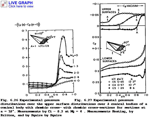
The results in Fig. 6.27 were obtained on three wings at the same Maoh member, chosen so that both nominally subsonic and supersonic leading edges are
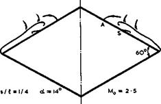
covered. The wings are compared at the same lift coefficient. Again, the character of the pressure distribution over the upper surface suggests the existence of leading-edge vortex sheets. This is confirmed by observation of the limiting streamlines in the surface, as obtained by an oil-flow technique, as at subsonic speeds. The flow separates along the leading edges and turns inward. An attachment surface (the position of which is marked by the letter A in Fig. 6.27) then divides the air which is directed immediately downstream from that which is drawn underneath the vortex sheet and flows towards the leading edges for a while until a secondary separation line (marked S in Fig. 6.27) is reached. It seems remarkable that this type of flow persists even when the leading edges are nominally supersonic.
Some experimental traverses of the flow field and also visual observations by D Pierce & D A Treadgold (1964) by means of a conical optical system indicate that a region with aoniaally-supersonic flow may exist above the vortex sheets, terminated by shockwaves, as sketched in Fig. 6.28. In this test, at a nominal 6s/£ of 0.57, there was a strong detached shockwave around the body (outside the field of vision) and primary separation from the leading edges. The flow then expanded around the outside of the vortex sheet to conically supersonic Mach numbers. It appears to be a general feature that the vortex
Previous Page
374
|
Fig. 6.28 Observed flow pattern over a rhombic cone. After D Pierce & D A Treadgold (1964) |
sheets are flatter and closer to the surface the higher the Mach number.
There are two shocks on either side of the body in the particular case of Fig. 6.28; one of them may be associated with the existence of secondary vortex sheets springing from secondary separation lines marked S, which seem to affect the shape of the primary sheet. Similar results have been obtained by V N Alekseev & A L Gonor (1974) but they observed a shock of X-shape.
J H В Smith SAG Kurn (1968) measured pressures on the conical body of Fig. 6.26 over an intermediate Mach number range from Mo = 0.4 to 1.1 .
They found that, as the Mach number increased subsonically, the lifting pressure field was maintained in an almost conical form further back towards the trailing edge. Their results are entirely consistent with those in Fig. 6.26. They suppose, however, that the highest velocity normal to a conical ray anywhere in the flow field is reached just outside the boundary layer over the wing, whereas the results in Fig. 6.28 suggest that critical conditions first occur above the vortex sheet, where the flow is directed inward and the velocity component normal to a ray is greater than that below the sheet.
These matters need further clarification.
Some other effects of compressibility, such as heat transfer to the surface of the body, have been investigated experimentally, e. g. by H Thomann (1962) and by К G Winter et at. (1975). The effects of non-conical shapes with ogee and gothic planforms have been studied by L C Squire & D S Capps (1959) and by L C Squire (1962). Possible types of flow near the leading edges and, in particular, conditions for subsonic flow separations to occur or, alternatively, supersonic expansions without flow separation have been discussed by A Stanbrook & L C Squire (1964). These matters will be taken up again below in Chapter 8. Here, we confine the discussion to wings within the Mach cone from the apex, which may be regarded as aerodynamically slender, and where the flow always remains basically subsonic in type because, as we have seen above, these are the shapes of practical interest for transport aircraft to fly up to Mach numbers of around 2.
6.4 Theories for separated flows. There have been several attempts to calculate the flow over slender wings with leading-edge separation, usually under the assumptions that the flow is conical and that slender-body theory can be applied. Early work by M Roy (1952) and (1964) and by R Legendre (1952) and (1964) and others has been summarised by J H В Smith (1964), and we mention
also early papers by Mac C Adams (1953) and by R H Edwards (1954). Here, we give a brief outline and a few typical results of a theory developed by К W Mangier & J H В Smith (1957), which was later improved by J H В Smith
(1966) . This approach brings out clearly some of the physical features of the flow.
The conical flow past thin flat delta wings is calculated for a model where only one primary vortex sheet is shed from each edge, i. e. secondary vortex sheets, as in Figs. 6.18 and 6.19, are not included. The wing is made into a streamsurface, and the boundary conditions on the vortex sheets are that these should be streamsurfaces and that the static pressure should be the same at points on opposite sides of the sheets, which means that the magnitude of the velocity should be continuous across them, in this flow where the total head is the same everywhere (see section 2.4, equation (2.44)). The final boundary condition, which excludes the trivial solution without vortex sheets, is that the velocity at the leading edge should be finite. The only mathematical evidence for the existence and uniqueness of a solution to this problem is the success of calculations like those by J H В Smith (1966), where the numerical treatment is such that the uncertainties in the calculation are reduced to a negligible level.
In principle, the vortex sheet could be subdivided into an outer part, extending from the leading edge towards the core and including a few spiral turns, and an inner part, where the asymptotic core solutions described in the previous section could be used and fitted to the outer solution. In principle again, an inner solution for a non-slender core eould be matched to cm outer solution where slenderness assumptions are made. As explained above, this would be a better representation of the physics of the flow than one in which slenderness is assumed throughout, but such a treatment has not yet been carried out. In Smith’s numerical method, the handling of a spiral vortex sheet containing an infinite number of turns would present some difficulty and so the entire inner part of it is replaced, so far as its effects on the remainder of the flow field are concerned, by a line vortex. This has been shown to be justified, in the previous section, but some difficulties arise in the treatment of the inner part. The circulation around the line vortex must increase in the streamwise direction, and thus a surface joining the line vortex to the end of the outer vortex sheet must exist, across which the streamwise component of velocity is discontinuous, although the crossflow component is continuous. We can position this cut along a streamsurface, but the pressure will be discontinuous across it. The best that can be done is to satisfy the pressure condition in the mean, by making the overall force on the cut and the line vortex zero.
With these assumptions and conditions, J H В Smith (1966) could compute the shape of the vortex sheets, the vorticity distribution along them, and the pressure distribution and loads over the wing surface for the various flow patterns sketched in Fig. 6.16. We have already seen that, in some region downstream of the apex, these results agree well with measured pressure distributions and with measured distributions of the bound vorticity in the wing (see Figs. 6.11 and 6.12). Fig. 6.29 shows calculated shapes of the vortex sheet and, in particular, the effect of increasing the extent of the outer sheet from half a turn around the centre of the core to one and a half and to two and a half turns (n is the number of pivotal points along the sheet). It is very satisfactory to see how the solution settles down. The variation of the shape of the sheet with а/к is shown in Fig. 6.30 (for n = 21). For the largest sheet, а/к = 1.5 , the inner turn is well removed from both the wing
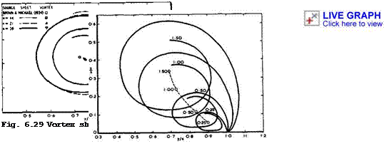 |
‘Fig. 6.30 Sheet shapes and vortex positions: n = 21 , various values of
-^L. . After Smith (1966)
and the plane of symmetry and has an almost Circular1 shape. The smaller sheets lie closer to the wing and become progressively flatter as a/к is reduced. The sheet always leaves the wing tangentially at the leading edge, though it turns inboard again so near to the edge for the smaller values of а/к that this is not apparent in the figure. One interesting feature of the solution for the longer sheets is that the radius of the spiral inner portion and the circulation along the sheet do not decrease monotonically towards the centre of the core, as in the asymptotic solutions discussed above, but there is a small oscillation with every turn around the values for the asymptotic core. This is also a feature of the solution for a slender sheet found by E C Maskell (1964, unpublished), which was mentioned in section 6.3.
Smith’s calculations lead to a simple approximate relation for the normal force on thin slender wings in conical flow:
|
|
![]()
![]()
![]()
The first term on the right-hand side is the linear component, as calculated by R T Jones (1946), and the second is the non-linear component induced by the leading-edge vortices. Note that the exponent in the non-linear term lies between 2 from (4.113) and 3/2 from (4.115) for rectangular wings.
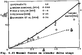
Meaningful comparisons between the forces on the wing as calculated by Smith and as measured at low speeds can be made if the experimental forces are derived from an integration of the surface pressure distribution in a region of conical flow near the apex. Fig. 6.31 shows values of the normal force
 LIVE GRAPH
Click here to view
CN obtained in this way: from measurements by P T Fink & J Taylor (1955),
D J Marsden et al. (1958), and D H Peckham (1958) (the latter are the extrapolated values Cjj(O) used in Fig. 6.10). Results obtained by С E Brown &
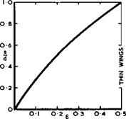
W H Michael (1954) from balance measurements on a thin delta wing at Mq = 1.9 are also included in Fig. 6.31 because the wing is aerodynamically slender (8s/А = 0.14) and because the flow can be conical up to the trailing edge at supersonic speeds. The results are presented in a form which brings in the similarity parameter a/(s/£) so that Smith’s answers all lie on one single curve. We find excellent agreement for the thin wings, but lower experimental values than those calculated for thicker wings (Peckham*s wing has a biconvex parabolic-arc section of t/c =0.12 at all spanwise stations). We have met this thickness effect before and shall explain it further below. We also see from Fig. 6.31 how large the non-linear lift can be by comparison with the dashed curve for the linear lift for slender wings with attached flow, according to (4.69) in section 4.3.
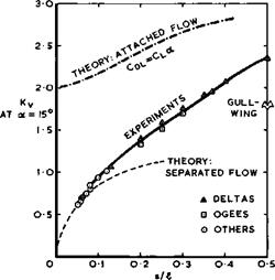
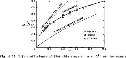
At this point, we may also consider lift and drag forces on complete wings at low speeds. The lift coefficient measured at a = 15° on a variety of uncambered thin wings is shown in Fig. 6.32, and the corresponding lift-dependent drag factor Ky in Fig. 6.33. Quite generally, the resultant air force is not normal to the mainstream but nearly normal to the chordal plane of the wing, because there is no suction force acting on the sharp leading edges, so that Cj)L – Cl(x * in contrast to the behaviour of unswept wings of high aspect ratio with round leading edges (see (3.30) in section 3.2). All the measured values lie roughly on one single curve for Cl and for Ky respectively.
 |
LIVE GRAPH
Click here to view “Fig. 6.33 Lift-dependent drag factors of flat thin wings at a – 15° and low speeds
They approach values from Smith’s theory for separated flow when s/£ becomes small: the effect of the trailing edge then matters less. We note, in particular, that the drag factor can be considerably smaller than unity, which is the minimum value for planar wings of high aspect ratio with linear lift (see (3.22) in section 3.2). It lies even further below the curve which would obtain if there would be linear lift only, as for attached flow, but no suction force. All this is a consequence of the large non-linear lift generated by the leading-edge vortex sheets: a given lift is generated at a much smaller angle of incidence than that required in an attached flow with linear lift only, and, in many cases, this more than compensates for the effective lift loss and drag increase caused by turning the resultant air force backward. However, we note also that, in the region of practical interest around
s/I = 0.25 , the lift could, in principle, be higher still and the drag lower than that which is obtained with flat wings. To improve on them poses a design problem which will be discussed below in section 6.6.
We can now proceed to consider theoretical work aimed at clarifying the effects which wing thickness has on the development of the leading-edge vortex sheets and on the forces on the wing, again under the assumptions that the wings are slender and the flow conical. These effects are strong and come out very clearly in a similarity theory developed by E C Maskell (1960), which provides insight into the vortex development by relating the growth with angle of incidence of the vortex systems above different slender wings to calculable similarity parameters. With these similarity parameters, the development of the flow field around each of a whole class of slender wings can be predicted, provided that the development of the field around one member of the class has been determined in some other way and is known. Maskell’s theory has been supported by extensive experiments at low speeds on a series of 17 conical wings, by D L I Kirkpatrick (1965), (1966), (1967), and by D L I Kirkpatrick & J D Field (1966). Supporting evidence for compressible flows has been provided by H Grauer-Carstensen (1969). These models were designed in such a way that the overall force could be measured on the front part of the model, where the flow could be assumed to be conical. Thickness effects have also been calculated directly by J H В Smith (1971) who extended his earlier theory for thin wings to thick conical shapes. The detailed behaviour of the sheet near the leading edge has been calculated by G J Clapworthy & К W Mangier
(1974) . H Portnoy & S C Russell (1971) have treated conical wings with small, but non-zero thickness. For details of these theories we refer to the original papers. Here, we can only give a brief outline and some results to illustrate the nature and magnitude of the effects.
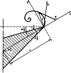
The cross section of the starboard half of a typical wing of the family to be considered is shown in Fig. 6.34. It does not have to be bounded by straight lines, and some of the wings tested had circular-arc cross-sections. The leading-edge angle & = nir and the dihedral angle пит/2 are measured in a plane perpendicular to the axis and are defined respectively as the included angle of the spanwise cross section at the leading edge and the angle between
|
Fig. 6.34 Nomenclature in Maskell’s similarity theory |
the line joining the leading edges and the line which bisects the leading – edge angle and joins the leading edge to the axis. The dihedral angle is positive when the wing’s axis lies below the plane through the leading edges. The angle of incidence a is defined as the difference between the actual inclination of the wing’s axis and its inclination when the aerodynamic normal force on the wing is zero. Note that the length s in Fig. 6.34 is not the semispan of the wing. However, force coefficients will be referred to an area S = s£. .
The first main result of Smith’s calculations is that, for non-zero leading – edge angles, the vortex sheets leave the wing tangentially to the lower surface. This is also a feature of Maskell’s theory. In the latter, the flow is considered as the sum of two velocity fields, the linear and the nonlinear. The linear field is associated with the attached flow around the wing, as assumed in slender-body theory, and yields a normal force which can be calculated for wings of any given cross-sectional shape. This normal force is directly proportional to the angle of incidence, and its rate of change with angle of incidence is directly proportional to the wing’s aspect ratio.
The non-linear field is associated with the vortex sheets which spring from the leading edges and their reflections in the wing surface. The two fields are adjusted so that the second cancels the singularity of the first at the edges and that the combined field has smooth outflow from the edges. Only small angles of incidence are considered so that it may be assumed that the distance of the vortex sheets from the leading edges is small compared with the lateral dimensions of the wing and that any interference between the vortex sheets springing from opposite edges can be ignored. The similarity theory shows that the non-linear velocity field depends only on the edge angle (n) , the dihedral angle (m) , an effective generalised incidence parameter (о/к)е and a scaling factor L. L and (а/к)е can be calculated directly from the linear flowfield.
The two theories of Maskell and Smith are complementary and are supported by the results from Kirkpatrick’s experiments. As far as the shape of the vortex sheet and the position of the vortex core are concerned, the experimental results for symmetrical rhombic cones indicate that, at constant angle of incidence, the effect of increasing the edge angle and hence thickness is to displace the vortex core steadily outboard. It moves initially upwards from its position for a flat plate and then down again towards the mean plane of the wing as the edge angle exceeds about 60°. The effect of dihedral on core position can be described in various ways, depending on the reference system: relative to the plane which bisects the angle between the upper and lower surfaces of the wing, the locus of the core, for a given angle of incidence, is further outboard on the wings with dihedral and closer to the wing surface on the wings with anhedral. Relative to a plane through both leading edges, the core is higher and further outboard with anhedral than with dihedral, as would be expected intuitively. When the similarity laws are applied to the original widely-dispersed points and the measured core positions are expressed in terms of the scaled coordinates £/L and т/Ь, then the scaled positions of the vortex cores above wings with the same leading edge angle all lie on one common curve. Similarly, if the scaled positions are plotted against the effective generalised incidence parameter (а/к)е, all the points for a given value of n lie again on one common curve, up to angles of incidence which are much higher than the small angles assumed in the theory. Values obtained for cross-sections bounded by either straight lines or circular arcs also lie on the same curves for given leading-edge angles. Thus
Kirkpatrick’s experiments confirm all aspects of Maskell’s similarity theory. They also confirm satisfactorily Smith’s calculated values for the variation of the total circulation in the vortex sheets with angle of incidence and with thickness. This circulation falls steadily with increasing thickness.
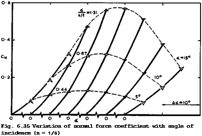 |
When edge angle and dihedral have such strong effects on the development of the vortex sheets, we must expect that the forces on the wing are also strongly affected. For dihedral this is demonstrated by an example for the conical normal force coefficient from Kirkpatrick’s measurements in Fig. 6.35. Wings carry less load if the edge angle is increased, or if the dihedral or anhedral
angle is increased. Both the linear and the non-linear parts of the lift are affected, and CN/(s/i.)^ can no longer be represented by a single curve as a function of a/(s/Jl,) , as in (6.38) for thin wings. A more general approximate relation has been introduced by Kirkpatrick (1968):
The factor a of the linear term has been calculated by Smith (1971) from slender-body theory for rhombic cross-sections:
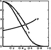
is related to the leading-edge angle 6 = шг, and where d(e) is a transformed value of the semispan, which is plotted in Fig. 6.36. Values for the factor b of the non-linear term and for the index p for symmetrical wings
|
|
|
Fig. 6.36 Values of parameters needed to determine the normal force on thick conical slender wings |
are also plotted in Fig. 6.36, from Kirkpatrick’s experiments. They depend mainly on the leading-edge angle, but there are slight differences in the value of b for different cross-sectional shapes. The reduction of the nonlinear lift by thickness may be very large, and this explains part of the discrepancies we noted in connection with Figs. 6.10 and 6.31.
There are many other theoretieat treatments of slender wings with leading edge separation. J E Barsby (1972) has extended Smith’s theory to wings with conical camber, and J E Barsby (1973) discovered an anomalous behaviour at very low angles of incidence, when separation appears to occur at a short distance inboard of the leading edge and the flow attaches smoothly at the edge. E S Levinsky & M H Y Wei (1968) applied Smith’s model and method to calculate combinations of thin delta wings with conical bodies of circular or elliptic cross-section. E S Levinsky et at. (1969) gave an extension of the theory to non-conical configurations. R W Clark (1976) has treated the general non-conical slender wing with straight, thin cross-sections; and a wing undergoing small plunging or pitching oscillations about a fixed angle of incidence has been calculated by R К Cooper (1975). D I Pullin (1972) and I P Jones (1975) have calculated the conical flow past a yawed slender delta wing. In most other theories, the flow model is simplified in varying degrees by using discrete line vortices, and we refer here to the versatile and general theory of К Gersten (1961), which has been extended to wing-fuselage combinations by H Otto (1974), and also to H C Garner & D E Lehrian (1963),
A H Sacks et at. (1967), and C Rehbach (1973). The simplest and earliest of
these theories is that by С E Brown & W H Michael (1954), where the vortex sheet is replaced by a single line vortex. This may be regarded as a degenerate case of Smith’s theory, and the example in Fig. 6.29 shows the result to be quite inaccurate. There are some indications that the accuracy is greater at small angles of incidence (see J E Barsby (1972)). An attempt to extend the Brown & Michael model to supersonic conical flow has been made by J P Nenni & C Tung (1971). The simplicity of the model allows non-conical shapes to be treated, J H В Smith (1957) and (1973) (see also R W Clark et al.
(1975) , and the effect of the trailing edge to be taken into account,
R К Nangia & G L Hancock (1968). Trailing-edge effects can also be treated by the theory of E C Polhamus (1971), in which the non-linear lift is equated to the leading-edge suction force predicted by the theory for attached flow. This theory has been extended to wings of general planform shapes by R G Bradley et at. (1973).
Because the slenderness assumption is made in most theories, the results are independent of Mach number and so show none of the important compressibility effects which we noted in Figs. 6.26 and 6.27. A theory by L C Squire (1963), which gives an estimate of the non-linear lift at supersonic speeds is, therefore, of special interest. He extends an earlier theory by D Ktlchemann (1955), where the principal assumption is that the vertical extent of the vortex sheet is of secondary importance so that the vorticity in the sheets and on the wing is taken to lie all in the one plane z = 0 . To retain the characteristic feature of the swirling motion around the vortex cores, the downwash is varied across the span. In a complete model of the flow, the wing would be represented by distributions of vortices and of sources and sinks, so that there would be an upwash on the upper surface outboard of some conical station По = Уо/х and a downwash inboard of it, while the flow would be kept parallel to the lower surface. The position no of the discontinuity would be just underneath the spanwise position where the core of the rolled-up vortex sheet would be: it cannot be determined from this theory. The sources and sinks can be ignored if only the lift is to be calculated and thus, in the simplest model, the downwash is assumed to be piecewise constant, and the angle of incidence of the wing is taken to be equal to the mean value of the downwash.
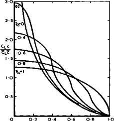
To retain the condition of smooth outflow from the leading edges, the solution is adjusted to give zero load along the edges. Solutions are obtained in closed form. They include the case of the flat wing of R T Jones (1946) with infinite suction at the leading edges when no = 1 (see Fig. 6.11). When Dq < 1 , the infinite suction peaks move inboard and the load is zero at the edges. Another characteristic of these solutions is that the spanwise distribution of the chord loading obeys the relation
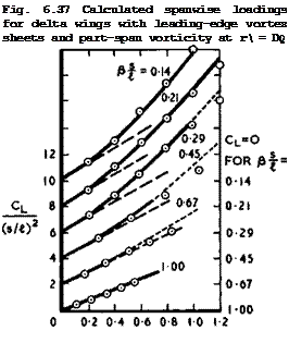
for wings with conical flow, as illustrated in Fig. 6.37. Only when, riQ = 1 does the spanloading become elliptic and tend to zero like (s^ – y^)* . This is quite a general feature and has been observed experimentally even for wings on which the flow is not conical. In this simple theory, it is assumed that ng varies linearly from the leading edge to the centre line as a increases from 0 to тг/2 . In the theory of L C Squire (1963), the slenderness assumption is not made and the lift is calculated by linear theory. Further, the function no(“) is replaced by one which makes the overall lift agree with that calculated by К W Mangier and J H В Smith (1959), which is given by a = 1, b = 4, and p = 2 in (6.39). Again, solutions in closed form can be obtained. Results for a series of delta wings are compared in Fig. 6.38 with experimental values, shown as circled points, which were obtained by
![]()
|
 LIVE GRAPH
Click here to view
CL
s/«
Fig. 6.38 Comparison between lift measured by W H Michael (1955) and calculated by L C Squire (1963)
I
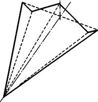 |
Fig. 6.39 Sketch of a conical gullwing
integrating pressure distributions measured by W H Michael (1955) at a Mach number Mg = 1.9 . The models covered a range of semi-apex angles from 5° to 32°, with a corresponding range of the slenderness parameter 8s/£ from 0.14 to 1.0. Squire’s theory (full line) is seen to give a good representation of the measured compressibility effects and shows, in particular, how the nonlinear lift tends to disappear as the leading edge becomes sonic, in keeping with the effects noted in connection with Figs. 6.26 to 6.28. Physically, the non-linear lift is associated with the suction peaks induced by the vortex sheets. There must be a limit to this, and the highest lift generated in this way obviously occurs when the pressure on the upper surface falls to zero, i. e. when vacuum is reached. For an infinitely thin wing with stagnation pressure on the lower surface, the maximum lift coefficient is 2/уМ^ , but
the theory must already be in error at values lower than that. In Fig. 6.38, the theoretical curves are shown dotted at angles approaching the vacuum limits; the measured values then lie below these curves. The dashed curves represent the linear theory for attached flow.
All the theoretical work described so far has been concerned with direct problems, i. e. the shape of the wing was specified from the outset, and not with design problems, in which the shape is required to emerge from the process as the result of specifying some aerodynamic property. One such design problem is an attempt to reduce the lift-dependent drag factor Ky. Since a slender wing generates a non-planar vortex wake, it might be hoped that values of Ky below unity would be obtainable. We have already seen (Fig. 6.33) that this turns out to be the case for flat wings, though only when the slenderness ratio s/A is very small (below about 0.1), and the angle of incidence fairly high. The reason why similar benefits cannot be achieved in more realistic circumstances (when s/St, is around 0.25) is that the distribution of circulation along the wake cross-section is no longer under the control of the designer. Having been shed from the leading edge, the vorticity is convected downstream and adopts a configuration which is only partially controlled by the shape of the wing. The lowest value of Ky would be achieved by a distribution of circulation which generates a uniform induced downwash all along the cross-section of the sheet in the wake, but it is clear, from the swirling character of the flow around the vortex sheets, that nothing
approaching a uniform downwash can be hoped for. In fact, we have already concluded from the results in Fig. 6.12 that the wake behind flat wings includes vorticity of both senses of rotation behind each half wing so that some upwash must be expected to occur along part of the sheet (see also Fig. 3.6). This is an inherently inefficient way of imparting downward momentum to the airstream; it constitutes a fundamental unfavourable characteristic of the vortex flow past slender wings.
We can think of one design principle which should bring about some improvement: to design a warped vying in such a way that the shedding of vorticity from the trailing edge is prevented altogether. Carrying this condition forward from an unswept trailing edge in the simplest way, we arrive at a wing in which the bound vortices lie perpendicular to the stream until they enter the leading-edge vortex sheets. For a conical wing, this corresponds to a uniform loading over the wing planform. To calculate such a shape by slender-body theory leads to some fundamental difficulty which does not arise in classical linear theory: there, a wing warped to have a specified loading is designed by assuming that it lies near enough to a reference plane for the boundary condition satisfied on the warped wing to be applied on that plane. An appropriate distribution of singularities related to the given loading is placed in the plane and the downwash induced by them is calculated and interpreted as corresponding to the surface slope of the warped wing. As explained above, this technique can. successfully be applied in the design of swept wings*, but it is quite inappropriate to the design of a slender wing in accordance with the design principle stated above. Within slender-body theory, the contribution of vortices lying across the stream to the induced downwash is neglected. The downwash which determines the wing shape is therefore induced, not by the vorticity in the wing, but entirely by the vorticity shed from the leading edges. This vorticity lies above the wing, and the shape and strength of the vortex sheet must be determined so as to make it a streamsurface across which the pressure is continuous. The wing forms part of the same streamsurface.
Its shape is also unknown, but we know that it carries no vorticity, in this model of the flow. This is a substantial problem, and there is no a priori evidence for the existence of a solution. J H В Smith (1971) has treated this problem, using the simple model with two isolated vortex lines by С E Brown & W H Michael (1954) to represent the sheets. He found a limited family of unrealistic solutions, but he also demonstrated that solutions of this new type do exist. More realistic solutions from a more complete model of the flow still remain to be found.
In spite of its oversimplifications, the quasi-linear model of D Ktichemann (1955) has also been used to design wings with a view to reducing the vortex drag; this method is at least in a form which can be applied to this purpose in that the loading can be prescribed and the shape to sustain it determined. Some preliminary design calculations have been made by J Weber (1971, unpublished) and the resulting models tested by D L I Kirkpatrick & P J Butterworth (1972). It was not attempted to even out the loading completely, as described above, but to go only some way towards this by loading up the middle part of the wing and thus filling in the large hole between the suction peaks near the leading edges (see e. g. Fig. 6.11). At the same time, it was attempted to design the warp in such a way that the suction peaks act on forward-facing * We recall here that the central region of a sweptback wing is also an
inefficient lifting device, involving the shedding of trailing vorticity of the wrong sign (see Fig. 4.22), and that camber and twist are needed to load up that region more effectively.
surfaces and thus have a thrust component. To reduce the drag by such thrust forces was first proposed and successfully demonstrated by G H Lee (1962). Intuitively, the wing shape to achieve these two objectives should be that of a gullwing, as sketched in its simplest form in Fig. 6.39. Compared with a flat wing with the same leading edges, the centre line of a gullwing is inclined at a higher angle of incidence; the trailing edge has an angle of dihedral over its inner part up to ‘shoulders’, and an angle of anhedral over its outer parts beyond the shoulders up to the leading edges. The shapes calculated by Weber were all of this kind, and the results of the windtunnel tests on thin conical models with s/l = 1/2 confirm that the general design trends were successful. Significant drag reductions of about 20% below the value for a flat wing in Fig. 6.33 were achieved for a lift coefficient around 0.5. The work has not been carried on beyond this preliminary stage and thus the main design problem of how far the vortex drag can be reduced in practice remains unresolved. Other camber designs for attached flow will be discussed in section 6.6.
Finally, we mention briefly another possible means of increasing the lift of a slender wing for a given drag by blowing a thin get of air out of the leading edges into the vortex sheets. This is a threedimensional equivalent of the get flap, discussed in section 5.2, which was proposed by D Ktichemann et al. (1956). It should increase the circulation in the vortex sheets, at the same time moving them outboard, and maintain a non-zero loading along the leading edge. Preliminary experiments by A J Alexander (1963) and by W J G Trebble (1966) demonstrated the physical reality of these effects. An inviscid flow model was proposed by С M P Morgado & A H Craven (1963), and E C Maskell (1964, unpublished) pointed out the essential feature that the jet streamlines, whose curvature determines the pressure difference the sheet can support, must be geodesics of the sheet. This idea was combined, by J E Barsby (1971), with the vortex-sheet representation by J H В Smith (1966) to provide a model of the flow both realistic and computable. He studied a flat-plate delta wing at an angle of incidence and used slender-wing theory. Conical flow was assumed to be maintained by increasing the blowing rate along the edge from zero at the apex. The initial jet direction was in the plane of the wing, at an angle to the leading edge that could be specified. Experimental investigations include balance measurements by R К Nangia (1970) and flow field surveys by J Spillman & M Goodridge (1972). A related scheme was studied by R G Bradley & W 0 Wray (1974). The outcome of the work on this threedimensional jet flap is that useful increments of lift can be obtained from moderate blowing momentum, with the jet inclined far enough backwards for most of its thrust to be recovered. The theory for inviscid flow predicts larger lift increments from blowing in a more forward direction. Apart from a theoretical study of the effects of blowing from the leading edges of a cambered delta wing by J E Barsby (1975), the two aspects conspicuously untreated so far are the effects of downward deflection of the jet sheet and of the interaction between the jet sheet and the leading-edge droop which is a design feature of slender aircraft. Leading-edge blowing thus appears attractive as a means of direct lift control, but it is not yet clear to what extent the complexity and weight of the duct system will offset the aerodynamic benefits. In this context, we refer also to the extensive investigations of E Carafoli (1962), (1969) and (1970).


