Our heavyweight helicopter equal in the world does not have
In Rostov started production of the most load-lifting rotary-wing car The Russian holding «Helicopt[...]

Everything about aircrafts and helicopters. News and events in aviation worldwide. Civil, transportation, military helicopters and airplanes.

Everything about aircrafts and helicopters. News and events in aviation worldwide. Civil, transportation, military helicopters and airplanes.

Everything about aircrafts and helicopters. News and events in aviation worldwide. Civil, transportation, military helicopters and airplanes.

Everything about aircrafts and helicopters. News and events in aviation worldwide. Civil, transportation, military helicopters and airplanes.


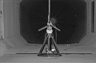
To examine the real effects of descent rate on the vortex wake streaming from a rotor the results of a wind tunnel test on a model rotor are presented.
The model installation is shown in Figure 2.19.
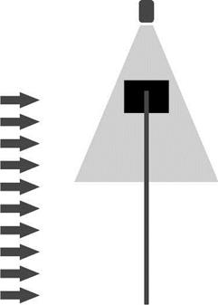
A particle image velocimetry (PIV) study was performed which enables laser light to be used to determine the flow velocity components in a geometric plane which is that swept out by the laser light beam – see Figure 2.20. In this experiment, the plane is normal to the rotor disc plane and includes the outer end of the blade and the initial part of the vortex wake. The velocity data are processed to give the vorticity variation across a part of the plane. Table 2.2 shows the vorticity maps for a range of wind speeds, which are effectively the descent rate of the rotor. For scaling purposes, the hovering induced velocity takes the value of 1.1 m/s.
The rotor rig details are:
|
Rotor speed |
1200 RPM |
|
Rotor radius |
254 mm |
|
Blade chord |
34 mm |
|
Number of blades |
3 |
|
Blade twist |
8° |
|
Collective pitch |
10° |
Table 2.1 Rotor flow states in axial flight
![]()
![]() In climb and hover the flow retains the streamtube concept. Throughout the length of the streamtube, the velocity is in a downward direction
In climb and hover the flow retains the streamtube concept. Throughout the length of the streamtube, the velocity is in a downward direction
Actuator disc theory can be applied with due regard to its inherent simplicity. This is known as the normal working state
At low rates of descent a toroidal type of vortical structure begins to form around the tip region. Actuator disc theory can be applied but this is the sensible limit of its use. There is a small amount of upward flow, relative to the rotor, but the majority is in a downward direction still
At moderate rates of descent – equivalent to the induced velocity in hover – the rotor becomes immersed in a large toroidal vortex type of structure. As already explained, this is a very unsteady type of flow state. Actuator disc theory is totally unsuitable for this situation. This is known as the vortex ring state. The velocity direction is varied across the rotor throughout this flow state
As the descent speed increases, the wake now begins to move above the rotor. Its characteristics are similarto the wake behind acircular disc, hence its name – the turbulent wake state. There is still a difference in velocity direction. It is difficult to justify using actuator disc theory unless the descent velocity is approaching twice that of the induced velocity in hover
As the descent rate increases further, the wake is now moved further above the rotor and the velocity is now upward throughout. The streamtube concept is now appropriate. Actuator disc theory can be applied with due regard to its inherent simplicity. This is known as the windmill brake state
The illustrations show the gradual transition from a hover flow state to that of a descending windmill brake state. The character is a balance of clean wake flow at each end of the table and that of a dispersing wake where the vortex ring state region is found. It should be emphasized that the illustrations are a mean flow. The vortex ring state is a very unsteady flight regime and this must be borne in mind.
![]()
|
Figure 2.19 Rotor rig in wind tunnel |
|
|
|
Table 2.2 |
Vorticity maps for a range of axial wind speeds |
|
|
Vz/Vo |
PIV image Vz/V0 |
PIV image |
|
0 |
 |
 |
 |
|
Table 2.2 (Continued)
 |
|
VZ/V0 PIV image VZ/V0 PIV image