
Our heavyweight helicopter equal in the world does not have
In Rostov started production of the most load-lifting rotary-wing car The Russian holding «Helicopt[...]

Everything about aircrafts and helicopters. News and events in aviation worldwide. Civil, transportation, military helicopters and airplanes.

Everything about aircrafts and helicopters. News and events in aviation worldwide. Civil, transportation, military helicopters and airplanes.

Everything about aircrafts and helicopters. News and events in aviation worldwide. Civil, transportation, military helicopters and airplanes.

Everything about aircrafts and helicopters. News and events in aviation worldwide. Civil, transportation, military helicopters and airplanes.


STATES OF FLOW
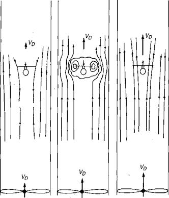
Just as in hover, there are two ways to analyze the rotor in vertical flight, the momentum method and the blade element method. In some vertical flight conditions, however, the relationships do not exist that were used to develop the hover methods. To obtain a physical understanding of the problem, let us examine the flow around a rotor mounted in an open-ended vertical wind tunnel as in Figure 2.1. Several different types of flight conditions can be simulated:
Hover
The tunnel fan is stopped and the rotor produces flow down through the tunnel. The governing momentum equation is:
|
|
Climb
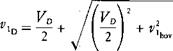
The tunnel fan is used to induce a downflow in addition to that of the rotor. Both the local flow at the rotor and the remote flow are down. The induced velocity at the rotor is:
 |
|
|
|
|
|
![]()
![]()
![]()
 |
or assuming constant thrust conditions:
where Vc is the climb velocity in feet per second.
Low Rate of Descent
The tunnel fan is used to induce a small upflow in the tunnel. For this case the flow is mixed. The local flow near the rotor is dominated by the rotor-induced velocity and is down, but the rest of the flow Field is up.
 |
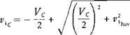
From a momentum standpoint, the equation for the induced velocity is:
This equation is semivalid for very low rates of descent; but, because of the mixed conditions, the continuous-flow assumption on which the momentum theory is based breaks down when the rate of descent is approximately a quarter of the hover-induced velocity.
