Our heavyweight helicopter equal in the world does not have
In Rostov started production of the most load-lifting rotary-wing car The Russian holding «Helicopt[...]

Everything about aircrafts and helicopters. News and events in aviation worldwide. Civil, transportation, military helicopters and airplanes.

Everything about aircrafts and helicopters. News and events in aviation worldwide. Civil, transportation, military helicopters and airplanes.

Everything about aircrafts and helicopters. News and events in aviation worldwide. Civil, transportation, military helicopters and airplanes.

Everything about aircrafts and helicopters. News and events in aviation worldwide. Civil, transportation, military helicopters and airplanes.


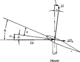
The conditions at the blade element for hover, climb, and descent are shown in Figure 2.2. In climb, the rearward tilt of the lift vector produces extra inflow drag, which is represented by extra power required to climb. In a steady climb, the helicopter is not being accelerated, so the rotor thrust has the same value as in
|
|
|
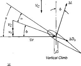
hover except for minor increases due to the increased vertical drag of the fuselage. This means that the average angle of attack is essentially the same as in hover; but, because of the extra inflow through the rotor, the blade pitch must be increased over the hover value. For calculations of the vertical climb, the combined momentum and blade element method developed for the hover analysis can be modified to include the effect of climb by using the general equation for induced velocity:
8л
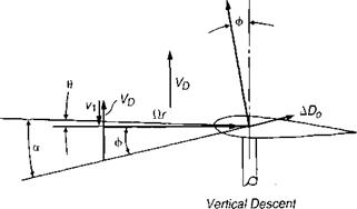
In descent, the blade element is subjected to air coming up at it from below. This reduces the rearward tilt of the thrust vector, thus reducing the power required. The upward velocity also means that the blade pitch must be reduced to hold the average angle of attack and the same rotor thrust.
At some rate of descent, the forward tilt of the lift vector is equal to the drag component. This is the condition of autorotation, since no torque need be
applied to maintain rotor speed. In an actual rotor, some blade elements will have more drag than the forward component of lift; but on other elements the situation will be reversed. Autorotation occurs when the integration of torque along the blade is zero—or, for an actual helicopter, is sufficiently negative to make up for losses in the tail rotor, transmissions, and accessories. All helicopters are equipped with an overrunning clutch between the transmission and the engine, so that the rotor does not have to drive a dead engine in autorotation.
Vertical autorotation is a balanced, steady flight condition in which the rotor thrust is equal to the gross weight and the rotor speed remains constant. For a given helicopter at a given gross weight, there is a unique combination of rate of descent, rotor speed, and blade pitch that defines the condition. Autorotation, once established, is stable: if the rotor speed decreases, the horizontal velocity vector at the blade element, Ctr, will shorten, and the lift vector will be tilted further forward, thus tending to increase rotor speed. The opposite effect occurs if the rotor speed increases from its original value. The pilot can control rotor speed by adjusting the blade pitch. A reduction of pitch initially decreases the rotor lift so that the rate of descent increases, thus tilting the lift vector forward and accelerating the rotor. As the rotor speeds up, the lift again reaches a value equal to the weight of the helicopter, and a new set of equilibrium conditions is reached with a higher rotor speed and a slightly different rate of descent than before the blade pitch was decreased.
For each helicopter, there is an upper and a lower limit of rotor speed that the pilot must observe. The upper limit is the speed at which the centrifugal forces in the blades and hub reach the structural design limit. The lower limit is the speed at which, in order to maintain rotor thrust equal to the gross weight, each blade element is being operated at or near its stall angle of attack. Once the blade elements stall, the drag increases rapidly, as shown in Figure 1.10 of Chapter 1, and becomes greater than any forward tilt of the lift vector can compensate. At this point the rotor slows down to a stop, and the flight becomes an accident. The upper limit is generally 10-20% above the normal speed for hover, and the lower limit may be as low as 20-30% below the normal speed.