Flow Visualization of Transient Rotor Wake Problems
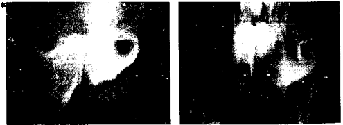
There are only a few experiments that have visualized the wake evolution of a helicopter rotor under nonsteady or transient operating conditions. The first was conducted by Taylor (1950) for a rotor with fixed collective pitch being impulsively started from rest. The balsa dust technique was used to seed the flow, which was illuminated by a light source. Figure 10.44 shows two images of the developing wake structure in a plane in the wake that intersects the rotor axis just shortly after the rotor was started. Of interest is that the wake shows evidence of a transient starting flow in the form of a vortex ring. This vortex ring is analogous to a starting vortex system for a wing set into rectilinear motion or undergoing a sudden change in angle of attack (i. e., the Wagner problem discussed in Section 8.10).
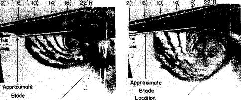
Results showing the formation vortex rings in a rotor wake were given by Carpenter & Friedovich (1953) for rapid increases in blade collective pitch and are also shown by Jessurun et al. (2001) for both rapid collective and cyclic pitch inputs. An example is shown in Fig. 10.45 from the work of Carpenter & Friedovich (1953), where it is apparent that the individual tip vortices pair-off in the wake below the rotor during the initial stages of wake development and soon form into coherent bundles of almost toroidal rings of concentrated vorticity. Just after the collective pitch input is applied the tip vortices can only convect relatively slowly away from the rotor because of the initially low thrust and low induced inflow. Therefore, the tip vortices initially lie in close proximity to each other, and their respective induced velocities create a tendency for them to pair about each other. This pairing tendency is the main reason for the formation of a ring of bundled vorticity immediately below the rotor plane.
 |
After the wake begins to develop and the inflow through the rotor increases, the newer trailed vortices begin to convect in a relatively higher wake velocity, and the starting ring is convected further down in the wake below the rotor. These vortex rings are present in
![]()
|
|
||
|
|||
|

the rotor wake for several subsequent rotor revolutions and can have a substantial effect on the overall time-history of the resulting wake developments, the developing inflow, and on the blade airloads. Also apparent from the various flow visualization studies that these starting rings of vorticity begin to break down as they are convected further away from the rotor. This suggests that the accurate modeling of close vortex filament interactions as well as the time accuracy of the problem will be critical in establishing good predictions of the overall rotor airloads when the flight controls are being manipulated under maneuvering flight conditions.


