General Dynamic Inflow Models
In many cases it is desirable to directly account for unsteady effects on net rotor forces and pitching moments. While the localized unsteady aerodynamic effects are clearly complicated, for some problems it is useful to seek a more global approach to modeling their
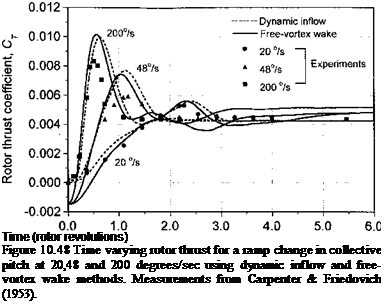
effects. This comes under the classification of dynamic inflow or so-called finite-state wake models. The principles range back to those of the steady inflow model used by Mangier & Squire – see Section 3.5.2. The idea in the dynamic inflow model is that the effects of the wake can he represented as a set of ODEs, that is, in state-space form. Consider, for example, a maneuver, where the unsteady effects will cause the inflow through the rotor to be different from that produced under steady level flight conditions. This will change the rotor forces and pitching moments, and so the rotor flapping response will be affected. See also Curtiss & Shupe (1971). The essence of these ideas can be attributed to Sissingh (1952), Carpenter & Friedovich (1953) and Joglikar & Loewy (1970), but many variations of the dynamic inflow theory and applications thereof have appeared in the literature. Crews et al. (1973), Ormiston (1976), Peters (1974), and Curtiss (1986) have put forth variations of the dynamic inflow theory and have showed that the effects can have an influence on rotor response and various problems in rotor dynamics and aeroelasticity. The most popular model of dynamic inflow is that of Pitt & Peters (1983), which has seen several applications in the literature – see Gaonkar & Peters (1986a, b) and Peters & HaQuang (1988). The ideas can also be extended to represent unsteady effects on 2-D airfoils – see Peters & He (1995).
Momentum theory can be used to relate the aerodynamic forces and pitching moments on the rotor to the inflow across the disk (see Chapter 2). The thrust, T, can be represented by the integral of the change in momentum through the rotor disk, that is,
pR рЪт
T — 2p I I v2r dxfr dr, (10.119)
Jo Jo
where v is the inflow velocity. Similarly, the pitching moment (positive nose-up) will be given by
![]()
 |
pR p2n
My =—2p I I v2r2 cos т/г d{f dr Jo Jo
and the rolling moment (positive roll to starboard) is given by
p R ріж
Mx = —2p I I v2r2 sinyj/ d}r dr. (10.121)
Jo Jo
A key assumption is the form of the inflow distribution over the rotor disk. As Section 3.5.2 has shown, a popular assumption is to use a linear distribution of the form
v = v(r, ifs) = Vo + vcr cos і(r + vsr sin ifr, (10.122)
where vo, vc, and ^ are the uniform, longitudinal, and lateral contributions to the inflow, respectively. This allows a coupling of the rotor thrust and pitching moments to the induced velocity field. This can be written in matrix form as
 (10.123)
where [L] is a coupling or “gain” matrix. The subscript “aero” implies that only aerodynamic contributions are to be included; rotor inertial terms are omitted. In a local momentum analysis of the problem, the [L] matrix is a diagonal matrix, where vo is related to Ct, vc is related to Сму, and is related to Cmx. These relations, however, may be coupled and the matrix will be fully populated. In forward flight, the coefficients in the gain matrix also become functions of the wake skew angle. Gaonkar & Peters (1986a, b) review the development of the gain matrix, although it appears that more experimental verification may be required to validate the assumptions made.
The ideas of a time lag in the development of the wake are introduced through the use of a time constant matrix [r] = [L][M], where [M] is a matrix of unsteady terms. The dynamic inflow model is now written as

 (10.124)
or
(10.125)
These ODEs can be used to relate the unsteady inflow to the rotor thrust and pitching moments. The time constants are also functions of the wake skew angle, which are derived from vortex theory. In the complete problem, the equations of motion of the blades must be introduced using a blade element approach. This provides the complete relationship between the blade loads, the rotor inflow, and rotor response.
Many refinements of the basic dynamic inflow approach can be found in the literature. The coupling and time-constant matrices have been derived from a number of other theories, including actuator disk and vortex theories. For extensive information on dynamic inflow modeling, see Johnson (1980). The most recent work on dynamic inflow has been put forth by Peters and colleagues – see Peters et al. (1987), Peters & HaQuang (1988), Peters & He (1989,1995), Peters et al. (1995), and Morillo & Peters (2002). Their work also encompass the classical theories of Theodorsen (Section 8.7) and Loewy (Section 8.8).
Dynamic inflow models have found utility for various problems in rotor aeroelasticity, as well as for helicopter flight dynamics – see Chen (1989) and Padfield (1996). However,
|


