Laser Scanning Pressure Measurement on Transonic Wing
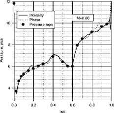
Torgerson (1997) demonstrated a phase-based laser scanning system for PSP measurements on a transonic airfoil in the Boeing Company model transonic wind tunnel. A 10% thick airfoil having a sharp leading edge and a small amount of camber was used, which was equipped with 19 pressure taps along the upper surface for a comparison with PSP data. The airfoil was coated with a Ruthenium – based PSP. The scanning system had a small air-cooled argon-ion laser for excitation and a PMT as a detector. The blue laser beam was modulated using an electro-optic modulator before scanning over the airfoil surface with a computer – controlled mirror, enabling the PMT signal to be processed using a two-phase lock-in amplifier. Both the phase and intensity signals were recorded during scanning over the airfoil such that a comparison between the intensity and phase methods could be made. Figure 9.30 shows a typical pressure distribution at Mach 0.8, indicating that both the phase and intensity methods compared favorably with the pressure tap data after in-situ calibration was applied. Nevertheless, phase-based measurements had the advantage that the wind-off data were not required.
|
Fig. 9.30. Pressure distribution on a transonic airfoil obtained using a laser scanning system based on the phase and intensity methods. From Torgerson (1997) |


