NON-LINEAR LIFT COMPONENT
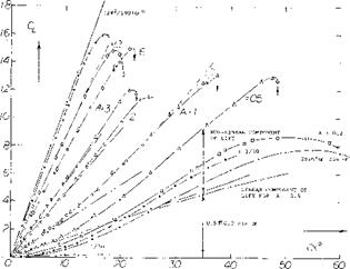
The lift curve slope of low A’ratio wings increases with angle of attack over the basic slope determined from equations 10 and 12 on figure 3. This non-linear increase of the lift curve slope is a function of the wing aspect ratio, its lateral edges and the component of velocity normal to the wing. The lift component above the circulation lift has been the subject of many investigations (4) and is a function of the flow about the lateral edges of the wing. In some ways it appears that the non-linear component of lift is caused by the drag based on the normal velocity component. Although the vortices at the lateral edges are on the upper surface of the wing they appear to be stable, thus giving some doubt to the drag concept where the Karman vortex street might be expected.
(6) Lifting characteristics of tapered wings:
(a) Anderson, 22 Tapered Wings, NACA T Rpt 572 & 627 (1936/38); also Analysis in Rpt 665 (1939).
(b) Whicker, Control Fins, TMB Rpt 933 (1958).
(c) Wolhart, With A = 2 to 6, NACA TN 3649 (1956).
(d) Allen, 3 Taper Ratios on Fuselage, NACA RM A1953C19.
(e) King, Taper-Ratio Seris, NACA TN 3867 (1956).
(7) It has been observed on a circular cylinder that the vortex street ceases to exist below a certain angle of attack.
(8) (a) Anderson, Systematic Investigation of 22 Tapered Wings, NACA T Reports 572, 627, 665. (b) Larger aspect ratios, NACA TR 669.
Larger A’ratios, NACA T Rpts 669 & 824, ARC RM 1708.
![]() Basic Flow. The flow pattern of slender wings can best be understood by considering the extreme case of A —>- 0. Physically, this condition can be produced by placing a long strip of material in a wind stream, at a longitudinal angle of attack. Since there is ‘‘no” leading or trailing edge, there cannot be any circulation as explained in Chapter II. Lift is still produced, however, by downward deflection of, and by imparting momentum onto a certain cross section or “slot” of, the air flow, This is accomplished by a pair of vortex sheets curling around the lateral edges, as shown in figure 4. This type of flow was observed from test of a flat plate with an aspect ratio of.25 (5,c) where tuft studies and flow measurements were taken. As shown in the illustration, the streamlines are spreading outboard on the lower side of such wings. The flow separates from the upper side and a strong vortex forms along each edge. It cannot be said, however, that all of the flow is separated. The inboard sides of the vortices impinge upon the wing, and they are the mechanism through which some fluid is transported from the lower to the upper surface. Eventually, the flow leaves the trailing edge in a manner similar to that of any conventional wing. We may consider the vortex system to be fully rolled up, however, essentially consisting of a pair of contracirculating vorcices.
Basic Flow. The flow pattern of slender wings can best be understood by considering the extreme case of A —>- 0. Physically, this condition can be produced by placing a long strip of material in a wind stream, at a longitudinal angle of attack. Since there is ‘‘no” leading or trailing edge, there cannot be any circulation as explained in Chapter II. Lift is still produced, however, by downward deflection of, and by imparting momentum onto a certain cross section or “slot” of, the air flow, This is accomplished by a pair of vortex sheets curling around the lateral edges, as shown in figure 4. This type of flow was observed from test of a flat plate with an aspect ratio of.25 (5,c) where tuft studies and flow measurements were taken. As shown in the illustration, the streamlines are spreading outboard on the lower side of such wings. The flow separates from the upper side and a strong vortex forms along each edge. It cannot be said, however, that all of the flow is separated. The inboard sides of the vortices impinge upon the wing, and they are the mechanism through which some fluid is transported from the lower to the upper surface. Eventually, the flow leaves the trailing edge in a manner similar to that of any conventional wing. We may consider the vortex system to be fully rolled up, however, essentially consisting of a pair of contracirculating vorcices.
Cross Flow. The manner in which the non-linear component of lift of slender wings is often explained is by stating it is equal to the force developed in the lift direction by drag, based on the velocity normal to the wing. If the component of velocity normal to the wing is V sin a then the force normal to the wing is
N = Co0.5? (V0 sinoif (13)
as explained in Chapter XV and in the book “Fluid Dynamic Drag”. Resolving N in the lift direction
^Ncosa; = Cp 0.5 ^ (V0 sin of)2- cosex’ (14)
where лЬ(у| is equal to the non-linear component of the lift. If the corresponding part of the total lift coefficient is лСрп then
АС|__П = Cq sin2c* cos o( (15)
Since there is some doubt that the non-linear component of lift is the same as that represented by the drag coefficient in normal flow we will substitute the factor k’ forCp in the above equation, thus:
ACLn – k’ sintf cos o’ (16)
The question on the use of CD in equation 15 is because of the apparent lack of a vortex street (7). Such a street can be understood to be produced by separation with alternately forming vortices. It is possible that the main component of flow V cos of tends to stabilize the vortices so that they form continuously and are carried away down stream. Thus, the vortices do not build up in size and separate as with a flat plate normal to the wing. When suppressing the lateral motion (by a “splitter” plate placed in its plane of symmetry) ordinary more or less symmentric and steady separation takes place. As shown in Chapter III of “Fluid Dynamic Drag”, the coefficient is then reduced to Cp =1.6. The magnitude of the factor k’ in equation 16 is thus doubtful, if really identifying it with drag.
Theory. Many attempts have been made to find a solution for the seemingly simple flow pattern of slender wings (4). For A = 0, which means the case of a very long straight strip of material exposed to a flow at a certain angle of attack, the lift function is
ACl = k’ sin or cosof (17)
For the wing with. A = 0 the potential lift slope, dCu /dof is zero at ex’ =0, figure 5. Thus the total lift coefficient of the zero A wing is that of equation 17. According to (4 a) k’ = 2. The close agreement with the drag coefficient in two dimensional flow in this case is only coincidental however.
+ NACA, t/c = 12% IN 2-DIM1L TUNNEL 0 NACA, TAPERED, A = 6 and =12
* NACA AND ARC, 0012, A = 6 Д NACA, CLARK Y, VARIOUS A1RATIOS О AVA, SHARP-EDGED RECTANG WINGS Г BRUNSWICK, A = 3 INVESTIGATION A ARC, RECTANGULAR, A = 0.5 and 2
* SCHOLZ, RECTANGULAR, A = 0.5 О NACA, RECTANGULAR PLATE
* WINTER, STRIP WITH A = 1/30
|
Figure 5. Lift coefficient of profiled, sharp-edged rectangular (and of some other) wings, as a function of angle of attack (adjusted for zero lift where necessary) for various aspect ratios. |
 |
£A ^ 2A<Xi c/b = 2 or – (19)
Consequently, for wings with A < 1, and 2 o(L = of , the increment in effective aspect ratio is found to be ДА ^ o’ . The effective aspect ratio AL = A + A A of such wings, therefore, increases with the angle of attack; and the lift increases at a rate higher than linear (9,c). Combining equations 5 and 19, replacing <X by the more correct term of sinof, and after introducing cosof (to indicate the difference between the vertical lift and the inclined normal force), the lift coefficient of wings with aspect ratios below unity may tentatively be
Cu = 0.5 ТГ sine* cosof (A + of ) (20)
![]()
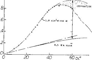
Figure 6. Lift characteristics of a thin flat plate having an The “second” component of lift in this equation is aspect ratio of A = 0.2, tested fully submerged in a
towing tank (3,f). = 0.5 Tf sin2- oc cosof ^ 0.5 V o’ (21)
Two Components of Lift. Wings never have a ratio A = zero. There are always edges which can be considered either to be trailing (thus causing some circulation) or leading (permitting some circulating flow to get around). A number of experimental lift functions are plotted in figure 5 for aspect ratios between 0. and 12. It is generally assumed that the lift of such wings is made up of two components, a linear one (due to circulation) equations 5 and 6, and a non-linear or quadratic term (due to the lateral-edge vortex flow). As an example, experimental results of a plate having an A’ratio of 0.2 are presented in figure 6. After subtracting a linear component found by equation 5, it is found that equation 17 agrees well with the experimental points when using k’ = 1.8.
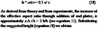
End Plate Effect. According to (9,a) a vortex sheet (rather than a “round” vortex) originates along each of the lateral edges. These sheets combine with the sheet coming from the trailing edge so that a U-shaped vortex wake is formed. One can then say that the long-chord wing leaves behind a vortex pattern very similar to that of a (short-chord) wing fitted with end plates. In rectangular wings, the height ЧТ of the imaginary end plates is assumed to be equal to the vertical distance between vortex core and trading edge. At A’ratios below unity, this height corresponds to oq = 0.5 or ; hence:
This time, the factor к is almost = 1.6. The end-plate formulation gives a qualitative explanation for the existence of two different components of lift in aspect ratios below unity. However, quantitative questions such as to the shape of wing planform and lateral edges remain unanswered.
|
|
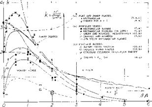
Figure 7. Second, non-linear component of lift, of plates and profiled lifting devices (wings) as a function of their aspect ratio.
![]()
![]() Non-Linear Component. Using equations 10 and 12 or the functions plotted in Figure 3, the linear circulation-type lift, potential flow lift, can be determined from experimental results such as in figure 5, for example. The non-linear “second” lift component of wings can thus be isolated from total values of lift or normal force. Such statistical data are plotted in figure 7 in the form of
Non-Linear Component. Using equations 10 and 12 or the functions plotted in Figure 3, the linear circulation-type lift, potential flow lift, can be determined from experimental results such as in figure 5, for example. The non-linear “second” lift component of wings can thus be isolated from total values of lift or normal force. Such statistical data are plotted in figure 7 in the form of
(Л C(_ /sin2 or) or (aCn /sin2 or ) (22)
This type of evaluation is somewhat uncertain insofar as the value of the linear component depends upon planform and lateral-edge shape of each wing tested. There cannot be much doubt, however, about the following conclusions:
(a) The value of ‘к’ to be used in equations 16 and 17 in order to obtain the second component of lift varies between zero and a maximum of 3.6.
(b) Sharp-edged plates show the highest values of kk’. They seem to meet the theoretical value of 2 as in (3,a) at A = 0.
(c) Wings with rounded lateral edges show ‘k’ factors which are considerably reduced, together with the effective span of such wings.
(d) Lift-producing efficiency is also affected by “round” planform. Wings with full-span and straight trailing edges are, on the other hand, most efficient as to the magnitude of the non-linea:: lift component.
Leading-Edge-Suction. Using an extension of the leading-edge suction analogy presented in (5,a, a) of chapter XVIII a theoretical method of finding the characteristics of low A wings with various planforms has been developed. This theoretical approach (4,g) finds the potential flow and non-linear lift terms for various wing planforms. For rectangular planform wings the theoretical potential flow lift agrees closely with that given on figure
5. The lift due to the vortices developed on the top wing surface as shown in figure 4 are given in terms of к as a function of A on figure 7. In the low aspect ratio range from A = 0.3 to 1.5 the theoretical leading-edge-suction analogy method appears to agree with the statistical data. This is especially true considering that the theory applies for wings with sharp edges.
|
FRONT ELEVATION SIDE ELEVATION
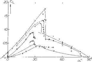
Figure 8. Characteristics of small aspect ratio wings with circular planforms and dihedral. Clark-Y Sections. |
In the absence of any solution really indicating the magnitude of the second lift term, the statistical results in figure 7 will permit to estimate that component in practical applications. Regarding the magnitude of k’ around A = 0.5, it is suspected that theories advanced so far (6) are not based upon the right mechanism. It is suggested that each lateral vortex not only produces lift by itself, but that it also increases the circulation over the rest of the wing area. Any end-plate effect (as in equation 18) may thus lead to the exponential increase as in figure 7, between A = 6 and 1. On the other hand, at A—0, there is no circulation which could be increased. According to these speculations, we end up with two non-linear components of lift; and it might not be a coincidence that k’ = 2 (as per equation 17) plus 1.6 (as per equation 21) equals 3.6 (as seen to be the maximum in figure 7).
(9) End-plate principle and non-linear lift:
(a) Mangier, in Yearbook D Lufo 1939 p 1-139.
(b) Expansion of the principle in (l, f).
(c) The principle is but a way of explaining that the volume (mass) of air onto which a downward momentum is imparted by the wing increases in proportion to the angle of attack and to the chord. That the principle is not perfect becomes apparent when considering drag due to lift of such small-A’ratio wings; see “Fluid Dynamic Drag”. The solution as in (4,f) assumes not only “end plates”, but a complete “box” of streamlines.
(10) Lift characteristics of streamline bodies:
(a) AVA Gottingen, Fuselages, Ergebnisse II (1923); see also Muttray in Lufo 1928/29 p 37.
(b) Bates, Various Fuselage Bodies, NACA TN 3429 (1949).
(c) NASA D-l 374.
(11) (a) AVA Gottingen, Flat Disk, Ergebnisse IV (1932).
(b) Zimmerman, 3 Clark-Y Wings, NACA TN 5 39 (1935).
(c) Mugler, Lenticular Shape, NASA TM X-423 (1960).
(d) Ware, Stability and Control, NASA TM X-431 (1960).
(e) Demele, With Fins and Flaps, TN D-788 and TM X-566.


