Nose/Leading-Edge-type (Edney Type IV and III) Interaction
Shock/shock interaction (with associated boundary-layer interaction) of Edney type IV, Fig. 9.15, is the most severe strong-interaction phenomenon. The type III interaction is less severe. Both can pose particular problems for instance at inlet cowl lips, Fig. 6.6, but also at unswept pylons, struts etc., because they can lead to both very large and very localized thermal and pressure loads.
We discuss some computational results for type IV interaction found on a cylinder [41]. The flow parameters are given in Table 9.5. They are from the
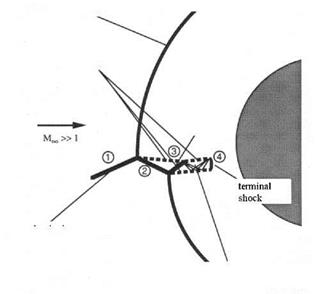
 bow shock
contact discontinuities („slip lines’“)
shock
impinging
shock
supersonic jet with isentropic expansion and compression regions
Fig. 9.15. Schematic of the Edney type IV shock/shock boundary-layer interaction
[41].
experiment of A. R. Wieting and M. S. Holden [42], supplemented in [41] by data from [43]. For a review and data see Holden et al. [44], and for a recent numerical study, e. g., [45].
|
Table 9.5. Flow parameters of the Edney type IV shock/shock boundary-layer interaction on a cylinder (D = 76.2 mm) computation case, air, laminar flow [41].
|
Consider the flow structures shown in Fig. 9.15. The basic flow field can be characterized by a smooth bow shock, whose distance from the surface of the cylinder can be estimated with the help of eq. (6.123) in Sub-Section 6.4.1 to be A0 « 0.23 Rb. The impinging shock wave with the shock angle 9imp = 18.11° divides the free-stream flow ahead of the cylinder into two regimes.
The upper regime (1), above the impinging shock, contains the original undisturbed flow. The lower regime (2), below the impinging shock, contains an upward deflected uniform “free-stream” flow with a Mach number Mdefl = 5.26, which is smaller than the original MTO. The flow-deflection angle, which
is identical with the ramp angle that causes the impinging oblique shock (the boundary-layer displacement thickness on the ramp being neglected), is S = 12.5°.
In the lower regime the “free-stream” flow has a density pdeft = 3.328рж. The density increase across a normal shock then would be p2,defl/рж = 16.91, compared to p2,orig/рж = 5.568. (2,orig (= 2,original) denotes the values behind the bow shock without the interaction.) This would give with eq. (6.123) for the isolated deflected flow a shock stand-off distance A0,defi & 0.1 Rb.
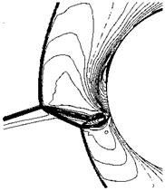
Of course, eq. (6.123) cannot be applied in our problem to estimate the shock stand-off distances in the upper and the lower regime. However, the ratio of these, found with the help of eq. (6.123) (A0,defl/А0,orig & 0.44), and that of the smallest computed stand-off distances measured in Fig. 9.16 (A0,defi/А0,orig & 0.5), are not so far away from each other.
|
Fig. 9.16. Computed Mach number isolines of the Edney type IV shock/shock boundary-layer interaction [41]. |
Edney’s different interaction types are characterized by the location in which the impinging shock wave meets the bow shock of the body. If this point lies rather low then two shocks of different families meet and cross each other, see Fig. 6.15 b). This is the type I interaction. Our type IV interaction case obviously is characterized by an intersection of shocks of the same family near the location where the original bow shock lies normal to the free-stream, Figs. 9.15 and 9.16, although this is not fully evident from the figures. Actually the finally resulting pattern shows two of these intersections of shocks of the same family, each well marked by the emerging third shock and the slip line.
Between these two slip lines, Fig. 9.15, a supersonic jet penetrates deep into the subsonic domain between the deformed bow shock and the body surface. The final, slightly curved, normal shock, Figs. 9.15 and 9.16, equivalent to a Mach disk in a round supersonic jet, leads to a large density increase close to the body surface.
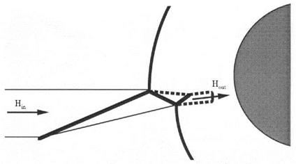
The supersonic jet has a particular characteristic, Fig. 9.17. It captures, due to the upward deflection of the flow behind the impinging shock wave by 6 = 12.5° in the lower regime, a considerable total enthalpy flux (puht)Hin, which then is discharged by the final normal shock towards the body surface (Hout ~ 0.2Hin).
|
Fig. 9.17. Hight of the capture area, Hin, and of the discharge area, Hout, of the supersonic jet in a Edney type IV shock/shock interaction [41]. |
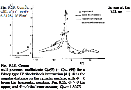
Because of this concentrated enthalpy flux, and the close vicinity of the final, slightly curved normal shock to the surface, a very localized pressure peak results as well as a very large heat flux in the gas at the (cold) wall, Figs. 9.18 and 9.19.
The maximum computed pressure in the stagnation point at the cylinder surface is pw « 775 px, and the maximum density pw « 310 pTO. The large heat flux in the gas at the wall is due to the locally very small thickness of the thermal boundary layer, 6T, which in turn is due to the large density there [36].
The maximum computed pressure coefficient cp/cp0 « 9.4 is somewhat higher than the measured one. The computed heat flux meets well the measured one. The reference data cp0 and q0 are the stagnation-point data for the flow without the impinging shock. The agreement of computed and measured data is not fully satisfactory. In any case a very strong local grid refinement was necessary parallel and normal to the cylinder surface in order to capture the flow structures.

Another problem is the slightly unsteady behavior found both in the computation (the computation in [41] was not performed with a time-accurate code) and in the experiment. Similar observations and a more detailed analysis can be found in [45]. In [36, 46] results are given regarding the wall pressure, the heat flux in the gas at the wall, and the radiation-adiabatic temperature for the Edney interaction types III, IV and IVa, the latter being a there newly defined interaction type due to high-temperature real-gas
effects. The results show that in all cases the type IV interaction gives the highest pressure and heat transfer peaks, but that no sharp boundaries exist between the various interaction types.


