Shock-wave patterns
In an earlier paragraph we described how a shock wave is formed at a speed of about three-quarters of the speed of sound, i. e. at about M = 0.75. On a symmetrical wing at zero angle of attack the incipient shock wave appears on both top and bottom surfaces simultaneously, approximately at right angles to the surfaces, and, as one would expect, at about the point of maximum camber (Fig. 11.12b). On a wing at a small angle of attack, even if the aerofoil section is symmetrical, the incipient shock wave appears first on the top surface only (Fig. 11 A) – again as one would expect, because it is on the top surface that the speed of the airflow first approaches the speed of sound.
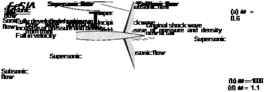
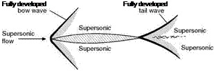
Figure 11.12 shows how the shock-wave pattern changes (on a symmetrically shaped sharp-nosed aerofoil at zero angle of attack) as the speed of airflow is increased from subsonic, through the transonic range to fully supersonic flow.
Between the formation of the incipient wave (at a Mach Number of about 0.75 or 0.8) and the time when the wing as a whole is moving through the air at a speed of sound (M = 1.0), the shock wave tends to move backwards, but in doing so becomes stronger and extends farther out from the surface, while there is even more violent turbulence behind it (Fig. 11.12c). At a speed just above that of sound another wave appears, in the form of a bow wave, some distance ahead of the leading edge; and the original wave, which is now at the trailing edge, tends to become curved, and shaped rather like a fish tail (Fig. ll. lld). As the speed is further increased the bow wave attaches itself to the leading edge, and the angles formed between both waves and the surfaces become more acute (Fig. 11.12c). Still further increases of speed have little effect on the general shock-wave pattern – but here we are trespassing on supersonic flight, which is the subject of the next chapter.
At each wave there is a sudden increase of pressure, and density, and temperature, a decrease in velocity, and a slight change in direction of the airflow. The thickness of a shock wave, through which these changes take place, is only of the order of 2 to 3 thousandths of a millimetre – they look thicker on photographs because it is not possible to get a perfectly plane shock wave in the experiment. The changes at the shock wave are irreversible, which is another way of saying that the losses, which lead to wave drag, cannot be recovered. It is interesting to note, however, that the incipient waves only extend a short distance from the surface, and leaks are possible round the ends of the waves; as speed increases the waves extend and there is less and less possibility of such leaks. It is interesting to note, too, that the decrease in velocity, which occurs behind the shock wave, means that when an aircraft is moving through the air, and a shock wave is formed, the air behind the shock wave begins to move in the direction in which the aircraft is travelling.
In addition to showing the shock-wave patterns, Fig. 11.12 also indicates the areas in which the flow is subsonic or supersonic. In (a) at M = 0.6 it is all
 |
Supersonic
 |
^Supersonic
Fig 11.12 Development of shock waves at increasing mach numbers
(a) Subsonic speeds. No shock wave. Breakaway at transition point.
(b) At critical Mach Number. First shock wave develops.
(c) At speed of sound. Shock wave stronger and moving back.
(d) Transonic speeds. Bow wave appears from front. Original wave at tail.
(e) Fully supersonic flow. Fully developed waves at bow and tail.
subsonic (clearly we are still in the subsonic region); at M = 0.8 the flow immediately in front of the shock wave is supersonic, but all the remainder is subsonic (we are now in the transonic region with both types of flow); at M = 1 the area of supersonic flow has increased but the flow behind the shock wave is still subsonic (as we shall learn later it is always subsonic behind a shock wave that is at right angles to the flow, it can only be supersonic behind an inclined or oblique shock wave); at M = 1.1 nearly all the flow is supersonic, but there are still small regions of subsonic flow, immediately in front of the leading edge at what is called the stagnation point where the flow is brought to rest, and immediately behind the trailing edge (we are still in the transonic region, but not for much longer); at M = 2 the flow is all supersonic – we are through the barrier (though to be strictly correct, unless the bow wave is actually attached to the leading edge, which will only happen if the edge is very sharp, there will still be a small area of subsonic flow at the stagnation point between the bow wave and the leading edge; and of course in the boundary layer itself the air immediately next to the surface is at rest relative to the surface, and most of the remainder of the airflow in the boundary layer is subsonic).
The figure also shows how the extent of the separated region, or thickened boundary layer tends to decrease with increasing Mach Number, and this suggests that as wave drag becomes relatively more important, boundary layer drag becomes relatively less so. This may also give a clue to the decrease in drag coefficient as we pass through the barrier (Fig. 11.7).
The reader should now be able to draw for himself the shock patterns, corresponding to those of Fig. 11.12 for an aerofoil inclined at a small angle of attack, and the exercise in doing so will help him to appreciate how and why shock waves are formed.
Figure 11B (on page 306) is a remarkable example of condensation and shock waves on an aeroplane in flight with, below, a Schlieren photograph of shock waves on a model of the same aircraft. More shock waves on an aerofoil are shown in Fig. 11F at the end of this chapter.


