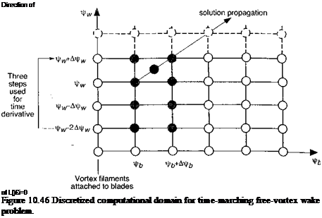
Simulation of Carpenter & Friedovich Problem
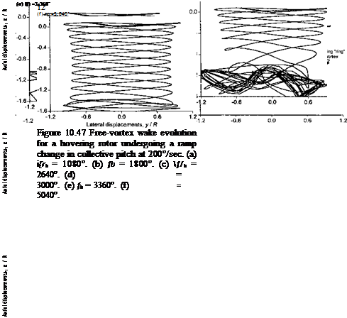
The time-marching free-vortex wake model can be applied to compute the evolution of the vortical wake structure for the Carpenter & Friedovich (1953) problem, as described in Section 10.8.2. Representative results are shown in Fig. 10.47 at selected times after the collective pitch input was applied. It is apparent that the trailed vortices initially pair off and bundle up below the rotor to form a vortex ring, as shown previously by the flow visualization images in Figs. 10.44 and 10.45. Immediately after the collective pitch input is applied the vortices trailed from the blade tips convect only relatively slowly away from the rotor because of the initially low thrust and low induced inflow through the rotor. In fact,
 |
by comparing the helicoidal pitch of the computed wake at early times versus later times in each case, it is apparent that the net inflow through the rotor builds up only relatively slowly over several rotor revolutions. Initially, therefore, the tip vortices lie in close proximity to each other, and their respective induced velocities create a tendency for them to pair about each other. This pairing tendency is clearly the main reason for the formation of a ring of bundled vorticity immediately below the rotor plane.
After the wake begins to develop and the inflow through the rotor increases, the newer trailed vortices begin to convect in a relatively higher wake velocity, and the starting ring is convected further down in the wake below the rotor. Notice that in each case the starting vortex structure is unstable and begins to show the presence of pronounced sinusoidal deformation modes or Kelvin waves (see Section 10.5.2). These waves grow in amplitude with time, and eventually cause the initial starting ring vortex system to break down as it convects into the far wake below the rotor. As the rotor induced inflow then approaches a steady-state value, the vorticity associated with the vortex ring is convected downstream well away from the rotor blades. After about 4-6 rotor revolutions (although this depends on the time rate of change of collective pitch), this starting wake has been convected about one and a half rotor radii below the rotor. At this point, any wake perturbations have been convected sufficiently far away from the rotor such that their influence on the rotor aerodynamics becomes small. The rotor wake then approaches a steady-state (periodic) condition with the vortex wake structure then taking on its more characteristic helicoidal form.
Figure 10.48 shows the predicted results of the rotor thrust for three values of the collective pitch rate (20,48, and 200° per second) along with Carpenter & Friedovich’s measurements. In each case, the predicted time-history of the rotor thrust response using either the dynamic inflow or free-vortex wake method shows good agreement with the experimental measurements. Notice that there is a lag in the development of the rotor thrust, which builds up and reaches its final value in about 2 to 4 rotor revolutions, depending on the collective pitch input rate. The intermediate values of the thrust show significant overshoots before

settling down to their final values. For the highest ramp rate of 200 deg/s, the thrust overshoot is about twice the steady-state value, confirming the significant effects of transient blade pitch inputs on the overall rotor wake evolution and blade airloads. Remember that the physics of this problem and the reasons for the lift overshoots is governed mainly by the temporal evolution of the vorticity trailed into the rotor wake, so that the lag in inflow development through the rotor is really a circulatory effect.


