INFLUENCE OF VISCOUS FLOW EFFECTS ON AIRFOIL DESIGN
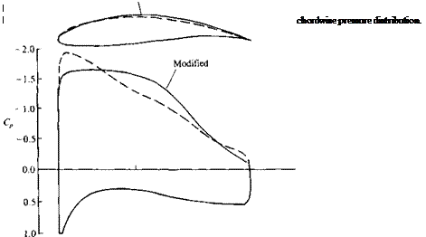
One of the earliest applications of panel methods (in their two-dimensional form), when combined with various boundary layer solution methods, was for airfoil shape design. Because of the simplicity of the equations, it was possible to develop inverse methods, where the programmer specifies a modified pressure distribution and then the computer program constructs the airfoil’s shape. Figure 14.14 depicts the sensitivity of the chordwise pressure distribution to the airfoil’s upper surface shape and emphasizes the importance of such
inverse methods. For more details on these airfoil design methods, see, for example, Refs. 14.7, and 14.9-14.11; and here we will attempt only a brief discussion of some of the more dominant considerations.
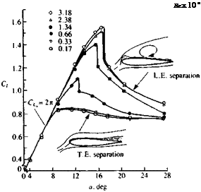
In order to estimate the effects of viscosity on airfoil design let us begin by observing the effect of Reynolds number on the performance of a two-dimensional airfoil. Figure 14.15 shows the lift coefficient versus angle of attack curve of a NACA 0012 airfoil and clearly the angle of attack at which
NACA 0012

 |
FIGURE 14.15
Effect of Reynolds number on the lift coefficient of a symmetric NACA 0012 airfoil. From Ericsson, L. E. and Reding, J. P., “Further Considerations of Spilled Leading Edge Vortex Effects on Dynamic Stall”, Journal of Aircraft, Vol. 14, No. 6, 1977. Reprinted with permission. Copyright AIAA. (Courtesy of L. E. Ericsson, Lockheed Missiles and Space Company, Inc.)
flow separation is initiated depends on the Reynolds number. Note that for the attached flow condition the lift slope is close to In, but at a certain angle (e. g., about a — 8° for Re = 0.17 x 10⁶) the lift does not increase with an increase in the angle of attack. This is caused by flow separation (see inset in the figure) and the airfoil (or wing) is “stalled.”
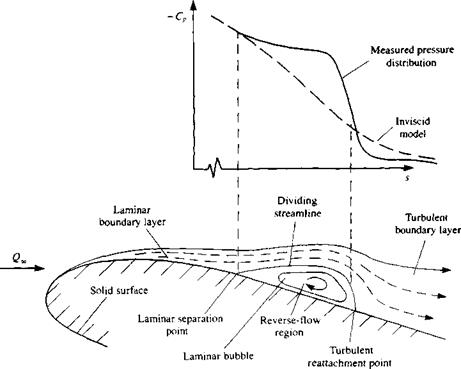
Let us, now, have a closer look at the boundary layer on the airfoil’s upper surface (that is, the suction side). If the free stream is laminar to begin with, then a laminar boundary layer will develop behind the front stagnation point (see Fig. 14.16). At a certain point the laminar flow will not be able to follow the airfoil’s upper surface curvature and a “laminar bubble” will form. If the Reynolds number is low (as in the lowest two curves in Fig. 14.15) then the laminar boundary layer will separate at this point. But if the Reynolds number increases, then the flow will reattach behind the “laminar bubble” and a transition to a turbulent boundary layer will take place. The effect of this “laminar bubble” on the upper surface pressure distribution is shown schematically in the upper inset to Fig. 14.16. Because of the modified
|
FIGURE 14.16 Schematic description of the transition on an airfoil from laminar to turbulent boundary layer and the laminar bubble. |
streamline shape the outer flow will have a higher velocity Ue, resulting in a plateau shape of the pressure distribution. Behind the bubble the velocity is reduced and the pressure increases, thus resulting in the sharp drop of the negative pressure coefficient.
Returning to Fig. 14.15 we can see that for increasing Reynolds numbers, as a result of the momentum transfer from the outer flow into the turbulent boundary layer, the airfoil separation is delayed up to increasingly higher angles of attack (upper curves in Fig. 14.15). This delay in the airfoil’s stall angle of attack (due to increased Reynolds number) results in higher lift coefficients and the maximum lift coefficient is called C, , whereas the flow separation now is a “turbulent separation.”
Another interesting observation is that for the low Reynolds number case, the flow starts to separate at the airfoil’s trailing edge, and gradually moves forward—this is called trailing-edge separation, and in this case abrupt changes in the airfoil’s lift are avoided. For the high Reynolds number cases the boundary layer becomes turbulent and the flow stays attached for larger angles of attack (e. g., cr=14° for Re = 3.18xl06 in Fig. 14.15). If gradual trailing-edge separation is needed at higher angles of attack (to avoid the abrupt lift loss) then this can be achieved also by having a more cambered airfoil section.
Some of the more noticeable considerations, from the airfoil designer’s point of view, become clear when observing the effects of the boundary layer with the aid of Figs. 14.11 and 14.15. The first observation is that the drag coefficient of the laminar boundary layer is smaller and for drag reduction purposes larger laminar regions must be maintained on the airfoil. However, when high lift coefficients are sought then an early tripping (causing of transition, for example by surface roughness, vortex generators, etc.) of the boundary layer can help to increase the maximum lift coefficient. Also, in many situations the same lifting surface must operate in a wide range of angles of attack and Reynolds number and the final design may be a result of a compromise between some opposing requirements. Consequently, to clarify some of the considerations influencing airfoil design, these two regimes of airfoil performance are discussed briefly in the following paragraphs.


