Our heavyweight helicopter equal in the world does not have
In Rostov started production of the most load-lifting rotary-wing car The Russian holding «Helicopt[...]

Everything about aircrafts and helicopters. News and events in aviation worldwide. Civil, transportation, military helicopters and airplanes.

Everything about aircrafts and helicopters. News and events in aviation worldwide. Civil, transportation, military helicopters and airplanes.

Everything about aircrafts and helicopters. News and events in aviation worldwide. Civil, transportation, military helicopters and airplanes.

Everything about aircrafts and helicopters. News and events in aviation worldwide. Civil, transportation, military helicopters and airplanes.


4.1 A Curved Thick Foil
in a Two-Dimensional Ground Effect
First, we consider an example of a flow problem for a moderately curved thin foil in the ground effect,1 and then present some results for thick foils. Essentially, as discussed at length in section 2, the procedure for the solution uses the assumption that, for h <C 1 and є = 0(h), nonlinear effects exhibit themselves mainly in the narrow channel under the foil. The foil and the corresponding coordinate system are shown in Fig. 4.1.
 |
у
 |
Coordinate System for a Foil in Ground Effect
The term “moderately curved” implies that the distances of points on the foil contour from the horizontal line у — h are of the order of О(h).
K. V. Rozhdestvensky, Aerodynamics of a Lifting System in Extreme Ground Effect © Springer-Verlag Berlin Heidelberg 2000
|
The complete problem for the perturbation velocity potential has the form
|
The solution of the upper flow problem can be written in a straightforward manner. The velocity potential at points on the upper surface of the foil is defined by the expression
¥>ui = тр Ц1 – re)–/ 3/s(£>e)ln(z-£)d£. (4-Ю)
І7Г 7Г Jq
Asymptotic expansions of cpUl near the edges are obtained in the following form:
• Near the leading edge,
![]()
![]() Ql і,1 -!(л і, Ai. ^2
Ql і,1 -!(л і, Ai. ^2
<^Ul – — ІПІ/+ —2/s(l) ^lni/ + і/— + —,
Z7T 7Г 7Г 7Г
![]() Jo
Jo
M = ~f ln(l ~ 0
Jo
• Near the trailing edge,
1 В В
(pUi ~-y’s(0)va. v+ v———- -, v-> 0, v = – x, (4.11)
7Г 7Г 7Г
si = y–y’s(Q)-Jo ШО-уК0)}-^’ B2 = ~J0 ^(£)ln£d£- (4-12)
• The channel flow region Д,
The nonlinearity of the ground effect exhibits itself mainly in Д. After introduction of a stretched vertical coordinate у — yjh into the full problem, we obtain the following channel flow problem with respect to the perturbation potential (f:
 0; (4.13)
У = У*(£,х); (4.14)
Note that in the upper flow limit, the influence of the condition at infinity is lost.
We seek <p as an expansion
щ = <рї + h2tf* + 0(h3), (<РІ<рГ) = 0(1), (4.16)
where
![]() <Pi = <Ph + h]n-<ph +h<pi.
<Pi = <Ph + h]n-<ph +h<pi.
Substituting (4.16) in (4.13)—(4.15), we obtain
(4.18)
i. e., for h <C 1 and є = 0(1), the flow under the foil is “almost” onedimensional2 and is governed by the elementary equation (4.19). The solution of this equation can be derived in the form
<^i — x + C —C2, (4.20)
J Vs
where the constants C and C2 are found from the boundary conditions at the ends of the interval x Є [0,1]. Because the function ys can be represented as
N
ys(S, x) = 1 + ‘^T/£jfj(x), (4.21)
3 = 1
the function (p* depends nonlinearly on є.
• The edge regions De
Near the edges of the foil, we introduce isotropic stretching of coordinates
As previously discussed in a more general case, the distances of the points on the foil from the horizontal line passing through the trailing edge are of the order of 0(h). So, with an asymptotic error of 0(/i2), the flow tangency condition can be imposed on the lines ys = jjf(l) (near the leading edge) and Vs = 2/s(0) (near the trailing edge). This simplification enables us to formally utilize the edge flow solutions obtained within the linear theory.
|
<Pie = O’lhpae + CL2h[18](pbe + azh2ys(l)v + a4/i, |
The leading edge flow velocity potential
v = v/ys{]), and /e is determined through the equation
![]() пй = 1- exp /e + /e.
пй = 1- exp /e + /e.
Near the trailing edge,
<Pte = hh2(fbe + b2h2v + b3h, i> = v – (4.25)
The solution for ірье is found from (4.23), substituting j/s(l) and y'(l) by 1 and y((0), respectively.
Matching gives the following results:
|
dip* |
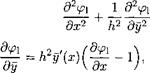
The boundary conditions to determine the constants of the solution (4.20) were found in the form
The lift coefficient is obtained by integrating the composite expressions for the pressure coefficients on the upper and the lower surfaces of the foil, i. e.,
where the upper and lower surface contributions to the pressure coefficients are defined by the formulas
We consider some examples:
|
2/10(2 + 0), + —(IT?)1" |
• Flat plate (ys = 1 + Ox, 6 = 6/h, 0 – pitch angle)
For vanishing 0 —» 0, formula (4.36) yields the linear result of Widnall and Barrows [40]; see formula (3.42). For the extreme ground effect (first term),
cy-Cl = TTe – (437)
It follows from (4.37) that
for 0 —^ 0, Cy ~ 0; for 0 —» oo, Cy ~ 1.
These results indicate that when both incidence and ground clearance tend to zero, permutation of the limits (6/h —>• 0 or 6/h —> oo) yields different results.
The limit 6/h oo implies that the trailing edge of the foil touches the ground before the pitch angle becomes equal to zero. It can be concluded from observation of (4.37) that, if one measures the ground clearance from the leading rather than the trailing edge, i. e.,
hie = h + 0, (4.38)
that is, the lift coefficient of a flat plate found from the nonlinear solution becomes linear in 0.[19] This conclusion holds exactly to the lowest order.
Figure 4.2 shows some results, obtained by using formula (4.36), in comparison with calculated data of Grebeshov et al. [137].
|
02 + 45c(2 + 0) 16Sc |
The next example is related to a parabolic foil, for which ys = 1 + Ox + 4Sc x(l — x),Sc = S/h, 6 = 6/h,
Qc — j (6 + 45c)2 + 16<5C,
C2 = —[0 + (0 + 45c)(l — Ci)],
7Г
![]()
|
[*(ln ~ ~ ~) + 4SC + [(в + 45c) In 7Г – 45c](l – C-h
For в —» 0 and Sc 0 we obtain the linear result (3.43).
 Another example is a flat plate with a flap at the trailing edge. For this case, ys = 1 + (0 + 5f) x, 0 < x < bf4 and ys = 1 + Sfbf + Ox, bf < x < 1, where bf is the chord of the flap and 5f represents the flap deflection angle, Si = Sf/h, _ _
(4.41)
С2 = -[6Ь{ + в + (в + 6{)(1-С1}-,
7Г
—5f [(1 — bf) ln(l — bf) + bf In bf]
+[5f(lnbf – bf + l) + (0 + 5f)ІП7Г](1 – C!)|.
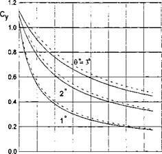
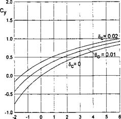
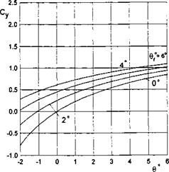
If в = 0 and 5f -4- 0, expression (4.41) yields the corresponding linear results; see formula (3.47). Some of the calculated results for the lift force coefficient of a moderately curved foil-in-ground effect are presented in Figs. 4.3 and 4.4.
|
Є" Fig. 4.3. The lift coefficient of a parabolic foil-in-ground effect versus pitch angle and relative curvature, h = 0.1. |
|
Fig. 4.4. The lift coefficient of a flat foil with a flap in the ground effect versus pitch angle and flap deflection angle, h = 0.05, 6f = 0.3. |
In what follows, some results are presented for a moderately thick foil[20] in a steady ground effect. For a foil with maximum relative thickness St, the ordinates of the upper and lower surfaces can be defined as
yu(x) = h + 0x + 6tfu(x), 2/i(ж) = h + 0x – Stf(x),
where 9 is the angle of pitch, and functions fu(x) and f(x) describe the positions of the upper and lower surfaces of the foil with respect to the chord line.
The lift coefficient is found in the form
![]()
 |
Су — C + C^/iln — + C3/1,
С2 = -[Уи(1)-1 + У,»(0)(1-С1)];
Сз — — v42+ai 1-ai+ln _ +(1—Cyi)[j/u(0)(ln7T—l)+j/{(0)—Бі]|;
l = ^, b2-a2 = J’u(o bijld
For the limiting case of zero clearance (h — 0), one can deduce from (4.42) the formula that corresponds to the situation when the trailing edge of the foil slides along a flat ground surface:
In the particular case of a flat plate for which yu = y = 1 + Ox, 0 = 6/h, the third term of (4.43), vanishes, and the formula is reduced to
Cy = 1 + H£ln£. (4.44)
Formula (4.44) is in satisfactory agreement with the exact theory of Tomotika and Imai [27] and Datwyler [28] up to angles of pitch of 5-6°. We can extend the range of validity of (4.44) by constructing an asymptotically equivalent expression
|
/Vu(0 hh-id*. К Jo £ |
![]()
![]()
 |
7Г
7Г 0 1 — 201п(7г/0)/7г’ which is in agreement with the exact theory up to angles 12-15°.
Consider a moderately thick foil with a flat lower surface and the upper surface in the form of a parabolic arc. In this case y = 1 + Ox, yu = 1 + Ox + 4Stx(l — x), St = St/h, where <St is the maximum relative thickness. The lift coefficient is found in the form
Cy – CyplM + (в + In £ – l), (4.45)
where Cyplate is the lift coefficient of a flat plate, as given by (4.36). If the trailing edge of the foil touches the ground, 0 = oo, and it follows from (4.45) that
~ і 20 7Г 8St
Cy — 1 H—- In — H—– .
7Г в 7Г