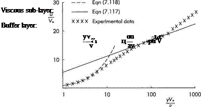
Regimes of turbulent wall flow
As the wall is aproached it has a damping effect on the turbulence, so that very close to the wall the viscous shear stress greatly exceeds the Reynolds shear stress. This region right next to the wall where viscous effects dominate is usually known as the viscous sub-layer. Beyond the viscous sub-layer is a transition or buffer layer
where the viscous and Reynolds shear stresses are roughly equal in magnitude. This region blends into the fully turbulent region where the Reynolds shear stress is very much larger than the viscous shear stress. It is in this fully turbulent nearwall region that the mixing-length theory can be used. The outer part of the boundary layer is more like a free shear layer and there the Reynolds shear stress is given by Eqn (7.111).
A major assumption is that the fully turbulent layer begins at a height above the wall of у «: <5, so that
 dr
dr
T = Tw + -7-у – I– ^ Tw
d У
Near the wall in the viscous sub-layer the turbulence is almost completely damped, so only molecular viscosity is important, thus
r = u^- = rw therefore m = —y (7.114)
dу V
In the fully turbulent region the Reynolds shear stress is much greater than the viscous shear stress, so:
r = —pu’v’ = rw
So if Eqn (7.112) is used and it is assumed that £m oc y, then
ф2“7? implyi”8 <7’115)
where we have introduced the friction velocity:
К = fbjp (7.116)
as the reference velocity that is subsequently used to render the velocity in the nearwall region non-dimensional.
Integrate Eqn (7.115) and divide by V„ to obtain the non-dimensional velocity profile in the fully turbulent region, and also re-write (7.114) to obtain the same in the viscous sub-layer. Thus
Fully turbulent flow:
|- = ад(^) + с2 (7.117)
Viscous sub-layer:
![]() h _yK V. і/
h _yK V. і/
where Ci and C2 are constants of integration to be determined by comparison with experimental data; and rj or y+ = yV,/u is the dimensionless distance from the wall; the length £+ = u/Vt is usually known as the wall unit.
Figure 7.37 compares (7.117) and (7.118) with experimental data for a turbulent boundary layer and we can thereby deduce that
![]() , yV„ du ——
, yV„ du ——
5 < -—- < 50 u— puV
v dy
Fully developed turbulence:
yV[42] „ du – j-j
—- >50 ц—С-ріїм1
v dy
The constants C and C% can be determined from comparison with the experimental data so that (7.117) becomes:
Logarithmic velocity profile:
![]()
 |
— = 2.54 in у *
Ci is often written as 1/k where к = 0.41 is known as the von Karman constant* because he was the first to derive the logarithmic velocity profile. Equation (7.117) is often known as the Law of the wall. It applies equally well to the near-wall region of turbulent pipe and channel flows for which better agreement with experimental data is found for slightly different values of the constants. It is worth noting that it is not essential to evoke Prandtl’s mixing-length theory to derive the law of the wall. The logarithmic form of the velocity profile can also be derived purely by means of dimensional analysis.*
The outer boundary layer
The outer part of the boundary layer that extends for 70 or 80% of the total thickness is unaffected by the direct effect of the wall. It can be seen in Fig. 7.37 that the velocity profile deviates considerably from the logarithmic form in this outer part of the boundary layer. In many respects it is analogous to a free shear layer, especially a wake. It is sometimes referred to as the defect layer or wake region. Here inertial effects dominate and viscous effects are negligible, so the appropriate reference velocity and length scales to use for non-dimensionalization are Ue (the streamwise flow speed at the boundary-layer edge) and 8 (the boundary-layer thickness) or some similar length scale. Thus the so-called outer variables are:


