Rotor-Empennage Interactions
 |
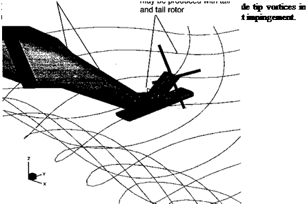
The interactions between the main rotor wake and the empennage (horizontal and vertical stabilizers and the tail rotor) are known to be particularly significant, yet systematic studies of the problem to understand the flow physics still remain relatively few. As shown in Fig. 11.20, the interactions involve vortex surface impingement. Lynn (1966) has discussed
some of the general problems associated with helicopter rotor-lifting surface interactions, but concentrating mostly on performance issues.
Historically, empennage designs on helicopters have proved problematic, mainly from a stability and control perspective, because large forces and moments are produced on the empennage by the rotor wake as its position changes with flight condition. As previously alluded to, resolving such problems can involve substantial costs for the manufacturer because of airframe redesign and associated flight retesting time. Good case histories of the stabilizer design are available in the literature [e. g., for the AH-64 Apache as documented by Prouty & Amer (І982) and Prouty (1983)]. Other documented examples are for the AS-360 discussed by Roesch & Vuillet (1981) and for the EH-101 as discussed by Main & Mussi (1990). It appears, however, that lessons are not always learned and the horizontal stabilizers of new helicopters continue to be hounded by main rotor wake interaction problems.
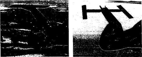
More fundamental investigations into the problem of rotor wake-lifting surface interactions include the work of Wheatley (1935), Makofski & Menkick (1956), and McKee & Naeseth (1958). Sheridan & Smith (1979) examined specific issues associated with wake induced empennage airloads in their seminal work on rotor-airframe interactions, as previously mentioned. Leishman & Bi (1994a, b), Foley et al. (1995), Funk & Komerath (1995), and Moedersheim & Leishman (1998) have studied the more detailed fluid dynamics of the interactions between rotor wakes and horizontal lifting surfaces. Torok & Ream (1993) obtained flight measurements documenting the wake interactions found on a helicopter with a T-tail empennage configuration. Frederickson & Lamb (1993) conducted wind-tunnel tests to further examine the issues. This research has led to a more optimized empennage design, as shown in Fig. 11.21. Moedersheim & Leishman (1998) have also examined the unsteady forces on a generic T-tail. In all tests the unsteady airloads and vibration levels can be correlated with the relative position of the main rotor wake boundary. Sheridan & Smith (1979) and Roesch & Vuillet (1981) have also shown that the turbulent rotor hub wake can have a considerable influence on the flow environment at the empennage location at high advance ratios – see also Berry (1997) for measurements and a more detailed discussion of this problem. This turbulence has been known to cause lateral buffeting or “tail shake” on some helicopters, which is only cured by suitable streamlining downstream of the rotor hub.
While rotor-empennage interactions have proved to be significant on helicopters, rotorwing and rotor-empennage interactions are particularly acute on compound helicopters and on tilt-rotor aircraft. In hover (helicopter mode), the wings of a tilt-rotor are directly below
|
(a) Original empennage design (b) Alternative empennage design
Figure 11.21 Two developmental versions of the empennage used on an advanced attack helicopter. |
the rotors and are immersed in the rotor wakes. This can produce strong wake-surface interactions [see Wood & Peryea (1991)] as well as unsteady airloads from blade-passage effects that are induced by the highly loaded proprotors. In forward flight (airplane mode), both the main wings and the tail surfaces are located inside the rotor wake boundaries. Under these conditions the proprotors induce nonuniform, 3-D velocity fields at the wings and empennage. Interactions between the rotor wake and the empennage are known to constitute a significant source of vibratory loads. See Clark (1987), McVeigh (1986), Schillings & Reinesch (1987), McVeigh et al. (1990), and Lesching & Wagner (1990) for a good discussion of the specific aerodynamic interaction problems associated with tilt-rotors. Like helicopters, the adverse effects are difficult to design out but some attempts can be made to minimize the otherwise deleterious effects on the performance of tilt-rotor aircraft.
 |
A low mounted aft stabilizer is a common design choice for a modern helicopter because it is structurally efficient; all the loads are carried directly into the tail boom so it can be of minimum weight compared to a T-tail. However, this stabilizer design tends to produce trim problems associated with transition from low-speed flight into hover, where the main rotor wake may suddenly move forward over the empennage location and so produce a nose-down pitching moment on the helicopter – see Prouty & Amer (1982). This problem is shown schematically in Fig. 11.22. Because the wake position relative to the empennage is affected by forward flight speed as well as climb or descent velocity, the aerodynamic angles of attack found at the empennage can be very sensitive to the actual flight conditions. Combined also with the higher total pressure obtained inside the main rotor wake, substantial changes in the forces on the stabilizer can be produced, which affect the pitching moments generated by the helicopter as a whole. If these changes occur suddenly or unpredictably, undesirable handling qualities can result – see Main & Mussi (1990). A high mounted tail or T-tail configuration places the tail out of the rotor wake for many flight conditions except for higher-speed forward flight or during descents. While a less efficient structural choice, Prouty & Amer (1982) suggest that this design is sometimes a good compromise in meeting the various requirements for a military helicopter.
 ‘ Stabilizer outside rotor wake boundary
Figure 11.22 Schematic showing interactions between the main rotor wake and the horizontal tail during transition from hover into forward flight.
11.3.1 Airloads on the Horizontal Tail
Consider now the airloads produced on the T-tail for the subscale experiment shown in Fig. 11.2. The primary factors influencing the airloads on the empennage include the highly nonuniform velocity field produced by the rotor and its wake, as well as an increase in total pressure inside the wake boundaries. For example, Fig. 11.23 shows measured flow velocity vectors in a cross-plane near the empennage location. Notice the signatures of the vortex bundles or “super-vortices” that are trailed from the lateral edges of the rotor disk, similar to those generated at the tips of a fixed wing aircraft – see, for example, Fig. 10.9. Similar results have been obtained by Le Pape et al. (2004) using PIV measurements. This wake rollup from the rotor disk induces a downwash on the horizontal tail, producing negative lift for this flight condition. The asymmetry of the wake roll up also produces a nonuniform sideward flow velocity and a force on the vertical fin.
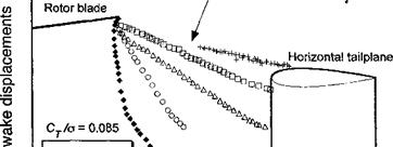
As shown in Section 10.2, flow visualization (i. e., smoke, shadowgraph) is an effective tool for finding the position of the tip vortices in the rotor wake. Typical results showing the wake boundaries at the longitudinal centerline for different advance ratios relative to the tail location are given in Fig. 11.24. The locations of the tail boom, vertical fin, and
![]()
![]()
![]()
![]()

![]()
![]()
![]()

 |
|
Body
Streamwise wake displacements
Figure 11.24 Measurements of the rotor wake boundary relative to an empennage assembly showing the sensitivity to variations in advance ratio. Data source: Moedersheim & Leishman (1998).
horizontal tailplane are shown for reference. It is clear that advance ratio has a significant effect on the wake position relative to the tail. At the lowest advance ratios the tip vortices are convected down toward the body surface, and then follow a trajectory that is almost parallel to the horizontal tailplane. An increase in advance ratio produces a higher wake skew angle, so the tip vortices are convected streamwise at an increasingly higher velocity. As expected, changes in the wake skew angle are largest at low advance ratios; this angle changes very little for д > 0.25. The rotor wake was found to impinge on the top surface of the horizontal tail for д = 0.25 and above. The flow visualization showed that, in the cases where direct, impingement of the tip vortices on the tail surfaces could be observed, they would burst and diffuse quickly. This suggests that strong local pressure and viscous effects are present.
Overall, it is found that the time-dependent pressures measured on the tail generally show more complex variations compared to on the body. This is not entirely unexpected because the environment at the empennage is much more 3-D than points further upstream. Also, as in the case of the body, the unsteady airloads are found to be closely related to the proximity of the rotor wake. For example, Fig. 11.25 shows representative time-dependent pressures measured at one location (Sensor #5 in this case) on the upper surface of the tailplane for a range of advance ratios at a constant rotor thrust and shaft angle. At low advance ratios (д <0.10) the rotor wake is convected relatively far below the horizontal tailplane, and the unsteady airloads are found to be negligible. As the advance ratio is increased, however, the unsteady airloads build up in intensity. Clearly this occurs because of the closer proximity of the rotor wake boundary to the tailplane.
The wake boundary comes very close to the tailplane between д = 0.20 and 0.25. At this condition the unsteady airloads seem to reach their maximum values. For advance ratios above 0.25, the separation distance between the wake boundary and the horizontal tailplane increases slightly, with a corresponding mild decrease in unsteady loading. Recall that for higher advance ratios the position of the wake boundary remains relatively unaffected by changes in advance ratio. The unsteady airloads are, therefore, maintained at the same overall magnitude. However, because the convection velocity of the individual vortex wake filaments increases with increasing advance ratio, a change in phase of the unsteady airloads with respect to the blade position will still be observed. It should also be apparent that the induced velocity field produced by the convecting tip vortices results in local angles of attack that vary in time at a fairly high reduced frequency. This can be established by computing the reduced frequency of the vortex passage at the tailplane from the equation
2д ‘ 1 ‘
The ratio с/R is about 0.25 for the configuration shown, so the reduced frequency of the flow at the tail for an advance ratio of 0.2 would be of order 2.5. Obviously this requires the mathematical modeling of the physics of this problem to be considered fully unsteady (Section 8.4). Also, if and when stall occurs locally on the tail, the high effective reduced frequency of the flow means that separation and stall may be more dynamic in nature. This adds yet an additional level of complexity to the mathematical modeling of the rotor-fail interactional aerodynamics problem.


