Boundary layer control by suction
Boundary layer control (BLC) may be utilized for several different reasons and can be accomplished in several different ways. High-energy air can be injected into the boundary layer at different positions along the airfoil with the purpose of increasing the energy of the slower-moving air in the boundary layer and thereby delaying separation. On the other hand, the boundary layer can be removed by sucking it off through spanwise slots or a porous surface. This may be done for one of two reasons. The first may be to stabilize the laminar boundary layer in order to delay transition to a turbulent boundary layer. This can significantly reduce the skin friction drag. The second may be to delay or prevent the separation of the turbulent boundary layer or the laminar layer.
Drag Reduction through Stabilization of the Laminar Boundary Layer
A comparison between the skin friction drag coefficients for laminar and turbulent boundary layers was given in Fig. 2-20 as a function of the Reynolds number. Depending on the particular shape of the body and the resulting static pressure distribution, the laminar boundary layer will undergo transition to a turbulent layer at some critical Reynolds number. For a flat plate, for example, with a zero pressure gradient the critical Reynolds number is about 3 x 10⁵. If the laminar boundary layer can be maintained to higher values of the Reynolds number, then from Fig. 2-20 it can be seen that a significant reduction in the skin-friction drag can be realized.
It is well known that the stability of a laminar boundary layer, that is, its tendency to become turbulent, depends both on its thickness and the shape of its velocity profile. Removal of a portion of the boundary layer by suction therefore has a twofold beneficial effect. It thins the boundary layer and, possibly even more important, it produces a more stable velocity profile.
261
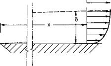
The exact analysis of the laminar boundary layer is accomplished by using the Navier-Stokes equations of motion for a Newtonian viscous fluid. A boundary layer velocity profile is shown in Fig. 10-1. If we assume that the boundary layer is thin (S « x), that the у-component of velocity is small (v « U), and that и changes gradually with x, compared with its gradient with y, Prandtl’s boundary layer equations are obtained.
ди 8u 1 dp d2u
dx dy pdx dy2 (1(M)
du dv fa + dy = ‘
In (10-1), the pressure gradient is written dp/dx rather than dp/dx, for the assumptions just listed result in the fact that the pressure does not vary with
|
У
Fig. 10-1. The boundary layer. |
|
у through the boundary layer; v is the kinematic viscosity and can be found in the standard atmosphere table in the Appendix. A classic solution of (10-1) is Blasius’ solution for the flat plate. In this case dp/dx = 0. If we let
|
where a prime indicates differentiation with respect to rj. This follows because
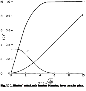 |
The nonlinear, third-order differential equation (10-4) can be solved in several ways: by expanding / in a power series in t and numerically on a
digital or an analogue computer; f /’, and /" are given in Fig. 10-2 as a function of?/.
It is difficult to define a boundary layer thickness, for the velocity approaches asymptotically to Ux as у increases. If we arbitrarily define the thickness S shown in Fig. 10-1 as the value of у at which и = 0.99Ux, then from Fig. 10-2
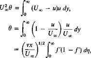
A more positive measure of the boundary layer thickness is the displacement thickness 5*; 5* is defined such that if the wall were displaced out-
![]()
|
UX(S – S*) = J и dy, |
|
<5* |
|
f00 / vx 1/2 1У p-™* /vx 1/2 (тг)lim ~ fW)]- UaoJ 4-°° |
|
|
|
|
|
|
|
|
|
|
|
|
|
|
|
|
|
|
|
|
|
|
|
|
|
|
|
|

![]()
|
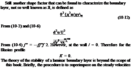
The ratio of S* to в is an important parameter, Я, used to define the shape of the boundary layer. For the Blasius profile |
|
5* |
|
8* >8. |
|
|
 |
|
|
|
|
|
|
![]()
 |
Ль) ^
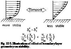
small perturbation velocities. Conditions are then investigated that will cause these disturbance velocities to grow with increasing x-distance downstream. Generally, the thinner the boundary layer and the fuller the velocity profile, the more stable the boundary layer. This is perhaps better understood by reference to Fig. 10-3.
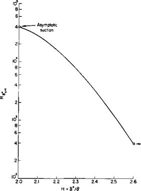
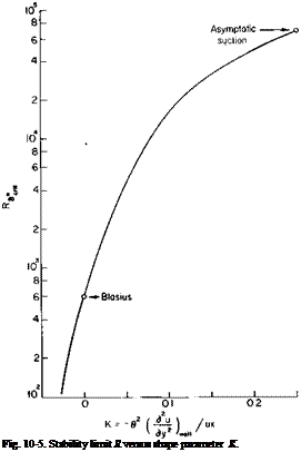
From numerous calculations and some experimental results the curves of Figs. 10-4 and 10-5 have been obtained. These curves which should give
|
Fig. 10-4. Stability limit Ra*ril versus shape parameter Я. |
comparable results give the maximum allowable boundary layer thickness in the dimensionless form of Rg,, which will maintain stability as a function of the shape of the velocity profile defined by H or K. Rg. is the Reynolds number based on and the local which may be a function of x.
UJx)S*(x)
 |
By applying suction to the boundary layer we can thin the layer and make the velocity profile more stable. This can be readily shown for the simple case of uniform suction over a flat plate, where the suction velocity is
assumed large enough to prevent the velocity profile from changing with x. If such exists, then du/dx = 0. From (10-1) so that v = constant = — v0, the suction velocity. Further, from (10-1)
du d2u – Vod~y = Vdf’ which integrates immediately to
![]() u(y) = UJl – e-^) v(x, y) = – v0.
u(y) = UJl – e-^) v(x, y) = – v0.
The above is referred to as the asymptotic suction profile and is obtained on a flat plate with uniform suction a distance x downstream of the leading edge of approximately
|
5* = —, |
 |
|
The displacement and momentum thickness for the asymptotic profile are
From Figs. 10-4 and 10-5 the asymptotic profile is seen to be considerably more stable than the Blasius profile, although the two criteria differ somewhat in the allowable values of Rjt.
A suction flow coefficient, Cq, is defined as
![]() ■ _ Q
■ _ Q
Q tj c
In (10-16), Q is the flow rate being removed by suction, U0 is the free-stream velocity, and Sw is the wetted area. For uniform suction Q = v0Sw so that CQ becomes
![]() (10-17)
(10-17)
For the asymptotic profile U0 = Ux, and using Fig. 10-4 as being more conservative,
Rs, = 4 X 10⁴.
"crit
Therefore
or, from Eqs. (10-15) and (10-17),
so that CQ = 0.000025. This is a surprisingly low suction rate to stabilize the boundary layer. Actually, the asymptotic profile does not exist over the whole plate but develops gradually from the leading edge. The intermediate
profiles are not so stable as the asymptotic and, for this reason more detailed calculations have shown that a CQ = 0.000118 is required to ensure that transition does not occur before the asymptotic profile is established. From the standpoint of using minimum power, we would apply the higher CQ value near the leading edge of the plate and reduce it toward the trailing edge.
Certain problems exist in attempting to stabilize a laminar layer. The wetted surface must be free from any roughness or at least from roughness greater than the displacement thickness of the boundary layer. Hence insects or rain impacting on the leading edge of a laminar flow wing could cause premature transition. Also vibration transmitted through the structure may be of sufficient magnitude to trip the layer. Finally, in attempting to suck off the flow, disturbances may be introduced that will cause transition.
One of the most promising schemes for sucking off the boundary layer to maintain laminar flow is to use rows of continuous narrow slots running along the surface and normal to the direction of flow (see Fig. 10-6). These
|
Fig. 10.6. Boundary layer control by suction through slots. |
slots are flush with the surface and are very thin. In order not to disturb the flow unduly, the width of the slots must be of the same order as the displacement thickness. Typically, this is about three to seven thousandths of an inch. The streamwise spacing of the slots depends on just how the boundary layer develops between slots. Current practice is to calculate the boundary layer growth on the basis of a continuous suction and to distribute the slots in accordance with the required CQ distribution. If the slots are all vented to a common internal manifold, we must relate the velocity through the slot to the difference between the external static pressure and the manifold pressure. If vs is the average suction velocity through a slot and t and s are the slot thickness and spacing, respectively, as shown in Fig. 10-6, the CQ will be
Cq = – JJ— (10-18)
Typically, s is of the order of one or two inches. Although still not completely proved with regard to practical application, laminar boundary layers have been maintained on aircraft wings to Reynolds numbers based on the chord – wise distance as high as 46 x 106.


