Our heavyweight helicopter equal in the world does not have
In Rostov started production of the most load-lifting rotary-wing car The Russian holding «Helicopt[...]

Everything about aircrafts and helicopters. News and events in aviation worldwide. Civil, transportation, military helicopters and airplanes.

Everything about aircrafts and helicopters. News and events in aviation worldwide. Civil, transportation, military helicopters and airplanes.

Everything about aircrafts and helicopters. News and events in aviation worldwide. Civil, transportation, military helicopters and airplanes.

Everything about aircrafts and helicopters. News and events in aviation worldwide. Civil, transportation, military helicopters and airplanes.


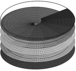
The actuator disc concept, taken together with blade element theory, serves well for the purposes of helicopter performance calculation. When, however, blade loading distributions or vibration characteristics are required for stressing purposes, it is necessary to take into account the real nature of flow in the rotor wake. This means abandoning the disc concept and recognizing that the rotor consists of a number of discrete lifting blades, carrying (bound) vorticity corresponding to the local lift at all points along the span. Corresponding to this bound vorticity, a vortex system must exist in the wake (Helmholtz’s theorem) in which the strength of wake vortices is governed by the rate of change of circulation along the blade span. If for the sake of argument this rate could be made constant, the wake for a single rotor blade in hover would consist of a vortex sheet of constant spanwise strength, descending in a helical pattern at constant velocity, as illustrated in Figure 2.25. The situation is analogous to that of elliptic loading with a fixed wing, for which the induced drag (and hence the induced power) is a minimum. This ideal distribution of lift, however, is not realizable for the rotor blade, because of the steadily increasing velocity from root to tip.
The most noticeable feature of the rotor blade wake in practice is the existence of a strong vortex emanating from the blade tip where, because the velocity is highest, the rate of change of lift is greatest. In hover, the tip vortex descends below the rotor in a helical path.
|
Figure 2.25 Helical wake |
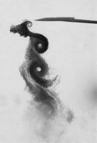
This can be visualized in a wind tunnel using smoke injection (Figure 2.26) or other means and is often observable in open flight under conditions of high load and high humidity. An important feature which can be seen in Figure 2.27 is that on leaving the blade the tip vortex initially moves inwards towards the axis of rotation and stays close under the disc plane; in consequence the next tip to come round receives an upwash, increasing its effective incidence and thereby intensifying the tip vortex strength.
Figure 2.28 due to J. P. Jones [6] shows a calculated spanwise loading for a Wessex helicopter blade in hover and indicates the tip vortex position on successive passes. The kink in loading distribution at 80% span results from this tip vortex pattern, particularly from the position of the immediately preceding blade.
The concentration of the tip vortex can be reduced by design changes such as twisting the tip nose-down, reducing the blade tip area or special shaping of the planform, but it must be borne in mind that the blade does its best lifting in the tip region where the velocity is high.
Since blade loading increases from the root to near the tip (Figure 2.28), the wake may be expected to contain some inner vorticity in addition to the tip vortex. This might appear as a form of helical sheet akin to that of the illustration in Figure 2.25, though generally not of uniform strength. Definitive experimental studies by Gray [7], Landgrebe [8] and their associates have shown this to be the case. Thus the total wake comprises essentially the strong tip vortex and an inner vortex sheet, normally of opposite sign. The situation as established by Gray and Landgrebe is pictured, in a diagram which has become standard, by Bramwell (p. 117) and other authors.
Figure 2.29 is a modified version of this diagram, intended to indicate the inner vorticity sheet, emanating from the bound vorticity on the inner part of the blade.
|
Figure 2.26 Real rotor wake |
The Gray and Landgrebe studies show clearly the contraction of the wake immediately below the rotor disc. Other features which have been observed are that the inner sheet moves downwards faster than the tip vortex and that the outer part of the sheet moves faster than the inner part, so the sheet becomes increasingly inclined to the rotor plane.